Load at launch.
Air braking at speed.
Keep ordinary rolling wheels and steering. Use body suction for launch grip and dedicated upward passages for braking. No moving wheel-collapse benefit is credited.

An airflow-led hypercar concept built around performance: launch grip, speed, high-speed deceleration and useful recovery. The original CryoPulse architecture now has connected models, opening-door CAD and explicit redesigns for the failures we found.
The future case assumes 230 kg of added system mass, an unachieved 0.15 m² external drag-area improvement, powered launch suction, a separate precharged 1 MJ / 200 kW traction pulse, revised fan/seal maps and sufficient tyre/brake capacity. The complete assumptions and failed cases remain available below.
The main passages stay central to the concept. In speed mode, air travels through an unobstructed rearward route. During braking, a selector sends that same stream through four upward outlets: the air gains upward momentum and the car receives a downward reaction, together with braking drag. The generator can extract power from that stream. A separate ground-pressure system supplies load when seals and electrical power permit.
Speed: preserve throughflow; bypass the heat exchanger when its obstruction costs more flow than cooling adds. These arrows explain routing and are not CFD streamlines.
Keep ordinary rolling wheels and steering. Use body suction for launch grip and dedicated upward passages for braking. No moving wheel-collapse benefit is credited.
A 200 kJ usable auxiliary-store target supports the revised pressure system. An optional separate 1 MJ traction store supplies a short 200 kW pulse; it cannot spend the braking reserve.
Keep useful component cooling and the N₂ expander on an accountable thermal path. The freezing-pressure branch can precharge an accumulator slowly for a short actuator pulse.
The acceleration reference uses Bugatti’s published Chiron times and a fitted effective wheel-power curve. The braking reference is fitted separately to the published stopping distances. These are aggregate envelopes, not a manufacturer digital twin. A held-out 400 km/h acceleration test was predicted about 7.9% too quickly, before the final all-point calibration. That discrepancy matters when assessing the proposed gains.
| Metric | Published Chiron | Conditional future case | Interpretation |
|---|
Published benchmark: Bugatti Chiron technical sheet and 2017 0–400–0 record report. CryoPulse values are model outputs under the assumptions shown here, with no Bugatti affiliation implied.
This selector uses launch suction and the same fitted engine envelope, with no traction pulse. It exposes the cases that lose performance as mass or drag rises. The headline future case additionally uses the separate 1 MJ traction pulse.
Auxiliary energy remains after the combined future run. The precharged traction store delivers 1 MJ, then wheel regeneration stores up to 1 MJ during braking. Recovery replaces part of the already limited wheel-braking work; it is never added as a second braking force.
Initial traction energy is an input. Fuel/engine work, drag and heat remain in the balance. This is recovery of finite vehicle kinetic energy.
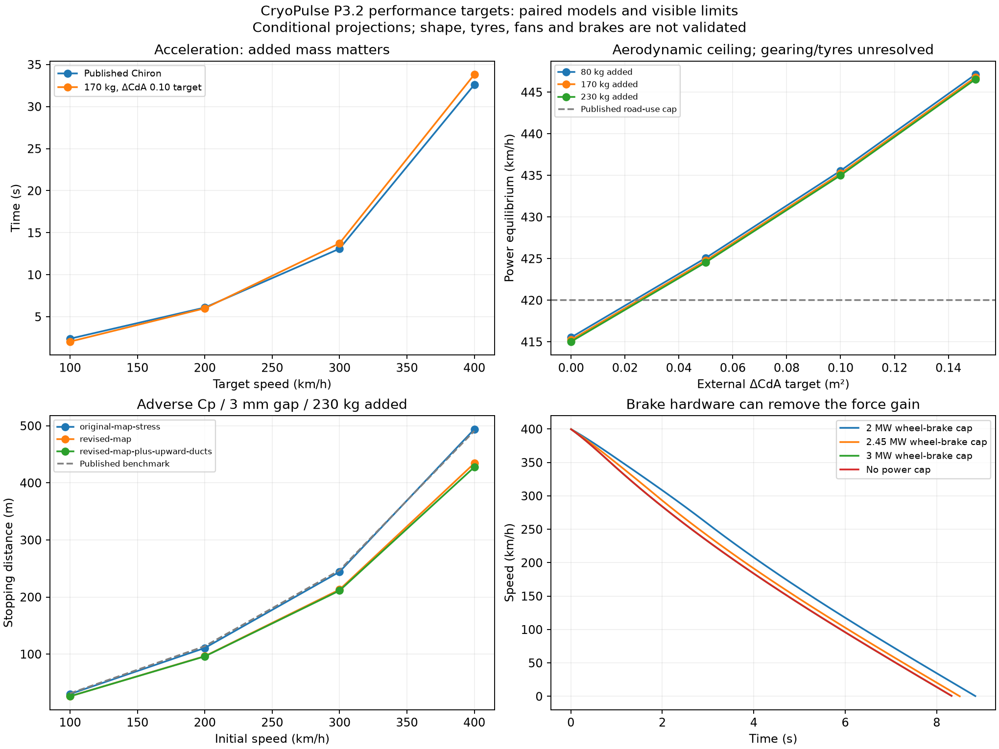
The unrestricted screen applies no speed limiter: approximately 447 km/h engine-only equilibrium and a brief 457 km/h peak with a fresh 1 MJ / 200 kW pulse reserved for this separate event. The pulse lasts 4.6 seconds. Gearing, tyres, thermal rejection and stability remain unvalidated.
| Unrestricted same-engine model | Boost off / equilibrium | Boost on / finite pulse peak |
|---|---|---|
| Reference power envelope | 431 km/h | 443 km/h |
| CryoPulse target case | 447 km/h | 457 km/h |
Both rows are models using the same fitted engine profile. The reference row is not a measured unrestricted Chiron result. A fresh 1 MJ store is reserved for this top-speed event; it cannot also be spent on the acceleration run without recharge. Read the unrestricted boost data.
The future case has a 230 kg all-in added-mass target and an external ΔCdA target of 0.15 m². The latter is about 21% of the assumed 0.72 m² reference drag area, before adding the new internal duct contribution. Neither value is achieved hardware. The earlier low-speed P2 CFD percentage is not transferred.
Without the traction pulse, the model’s 0–400 result becomes slower with added mass unless the shape gain is large enough. For a 0.10 m² improvement, the added-mass threshold for quicker 0–400 is approximately @@MASS_THRESHOLD@@ kg. This gives the design team a mass and aero requirement instead of an automatic improvement assumption.
Braking assumes that the added load can be used by the tyres and brake allocator. The wheel-brake power ceiling is 3 MW. Reducing that ceiling to 2 MW moves the 400 km/h projection from approximately 428 m to 477 m. Discs, pads, tyres, suspension and thermal rejection need hardware qualification.
| Observed model weakness | Design edit | Retest result |
|---|---|---|
| Simply lowering the tall side ducts breaks the body envelope. | Flatten the bay from 440 to 300 mm high; lower its centre 90 mm; widen the narrow sections 40 mm. | 16.7% more minimum flow area.Sampled cabin gap ≥19 mm; exact static arch intersection is zero. Dynamic steering/suspension remains ahead. |
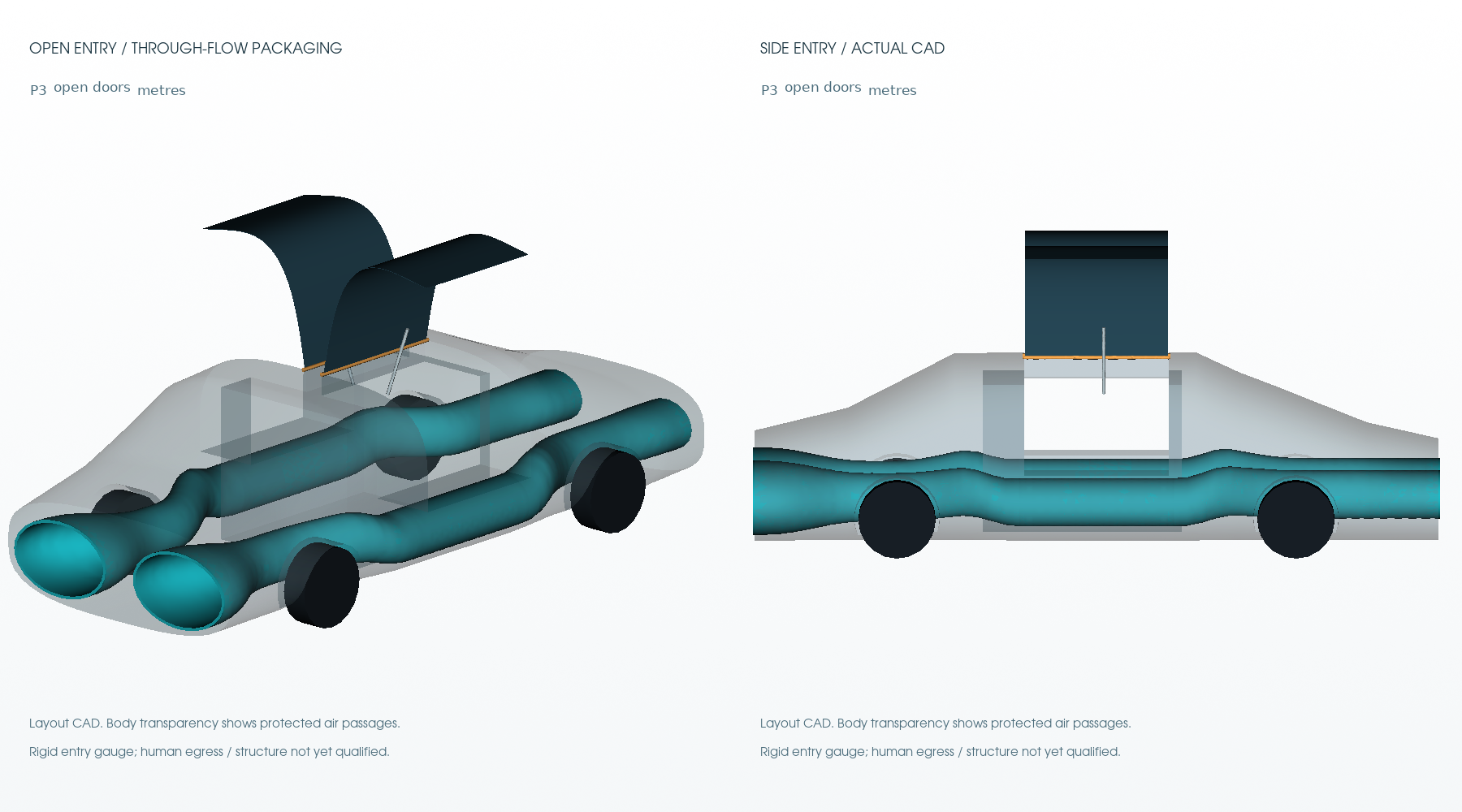
| Side passages block the entry space. | Move the bay below the upper opening and add curved gullwing panels. | 40 mm protected duct-to-door separation.17 solid-intersection poses plus a continuous swept-vertex bound. Entry gauge clears at the tested 50° position. |
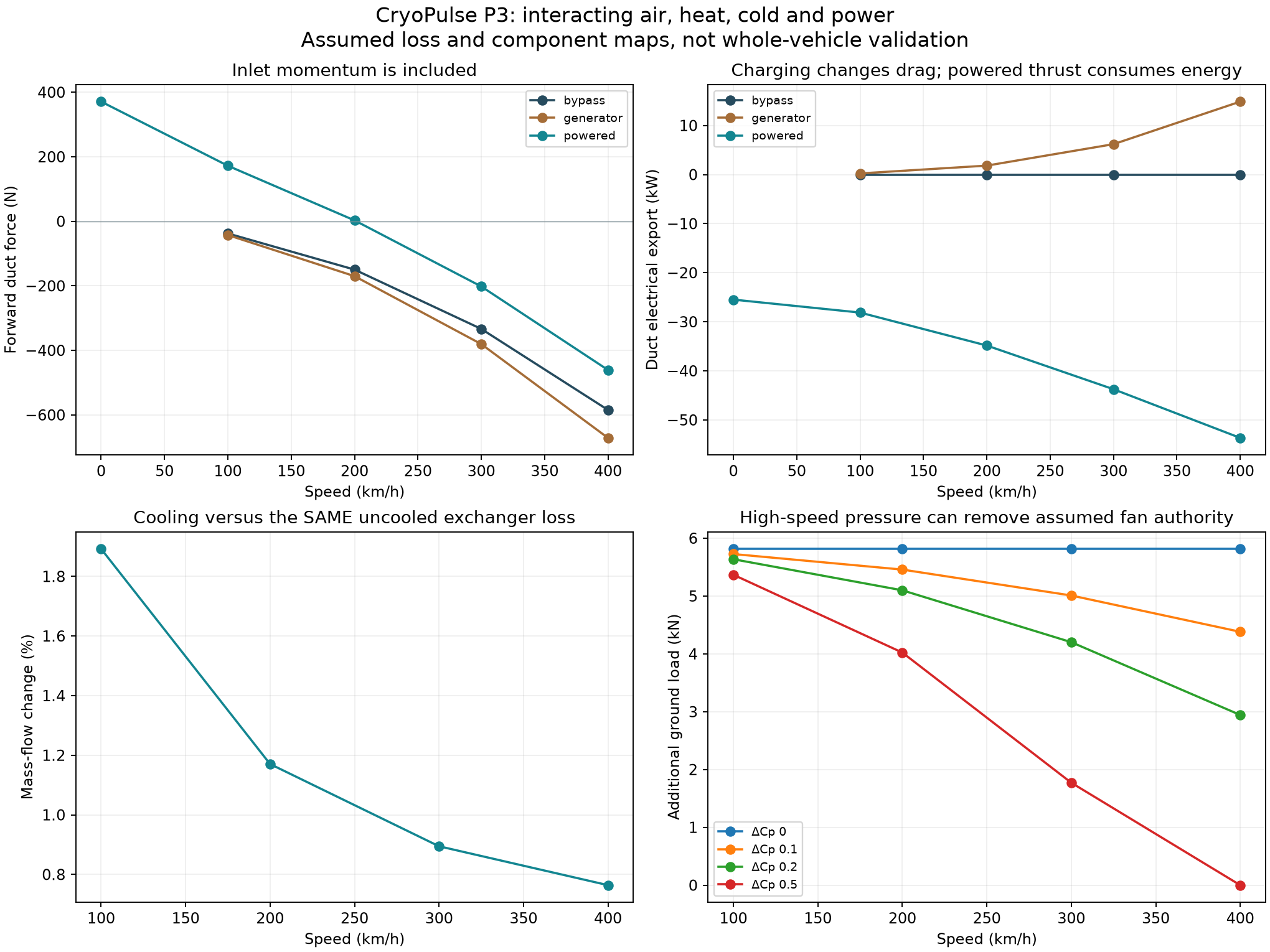
| The original 3 kPa fan has no pressure margin in the adverse 400 km/h / ΔCp 0.5 case. | Develop an equivalent higher-head map and a continuous outer seal, with internally restricted pressure sectors. | 5.815 kN at 3 mm gap, about 8.8 kW.Map target: 3 series stages × 2 parallel branches; not selected or tested fans. |
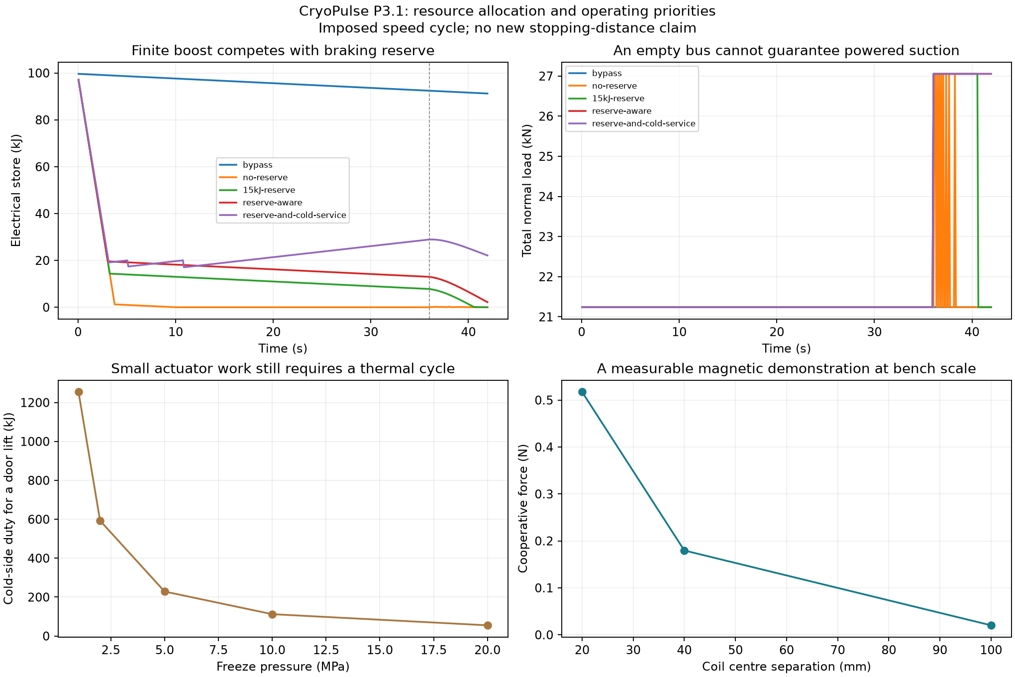
| Boost empties the store before powered braking. | Protect the reserve and use a separate traction pulse store. | Finite stores stay positive in the selected run.200 kJ auxiliary target; conservative worst-case braking reserve about 133 kJ. Converter peaks and rotor run-up need measurement. |
| The cold core adds resistance. | Install a real exchanger bypass and use a separate useful component-cooling loop. | Full-flow mode avoids the core.Cooling alone adds roughly 0.8–1.9% mass flow versus the same warm core; it does not always recover the core’s obstruction. |
| A rapid freezing cycle requires too much heat transfer for a small actuator event. | Precharge a finite hydraulic accumulator over 120 seconds. | About 539 W cold duty over the charge interval.The idealised pressure-cycle source can then supply a 307 J hydraulic pulse. Pressure hardware is not qualified. |
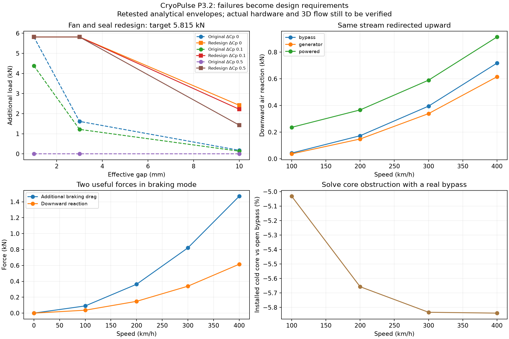
The redesign still loses suction capability at very large gaps or after some component faults. The road wheels retain their normal braking and steering role. The longitudinal one-branch-loss projection is approximately @@BRANCH_DISTANCE@@ m from 400 km/h; it does not establish yaw stability or safe fault response.
The entry model has real curved panels and a linkage screen. The newer brake layout connects four upward branches to the original paired passages, outside the entry region and static tyre envelopes. Inspect the actual STEP-derived meshes below. The body is a flow-exclusion envelope, not a completed structural chassis.
 Loading the actual CAD meshes…
Door motion rotates the actual closed CAD panels about the specified hinge axes. The actuator display follows its specified linkage endpoints. The upward-brake layout is a connected packaging candidate; its rear-outlet selector, flush speed-state covers, turn vanes and distribution controls remain detailed engineering work. No solved flow is implied by this view.
Maximum height at the 80° parked opening. The motion reaches about 2.53 m total width during the swing. The sill is 600 mm high over the duct: human ingress and step/handhold design still need a full-scale mock-up.
Nominal 4 mm composite panel plus a 2 kg hardware allowance. Two doors need about 307 J of opening energy at the assumed actuation efficiency. Wind substantially increases cylinder load.
Four circular outlet bores share the original air stream in braking. Their voids intersect the main flow volume; the candidate branches have zero solid overlap with the cabin, static tyres or tested door poses.
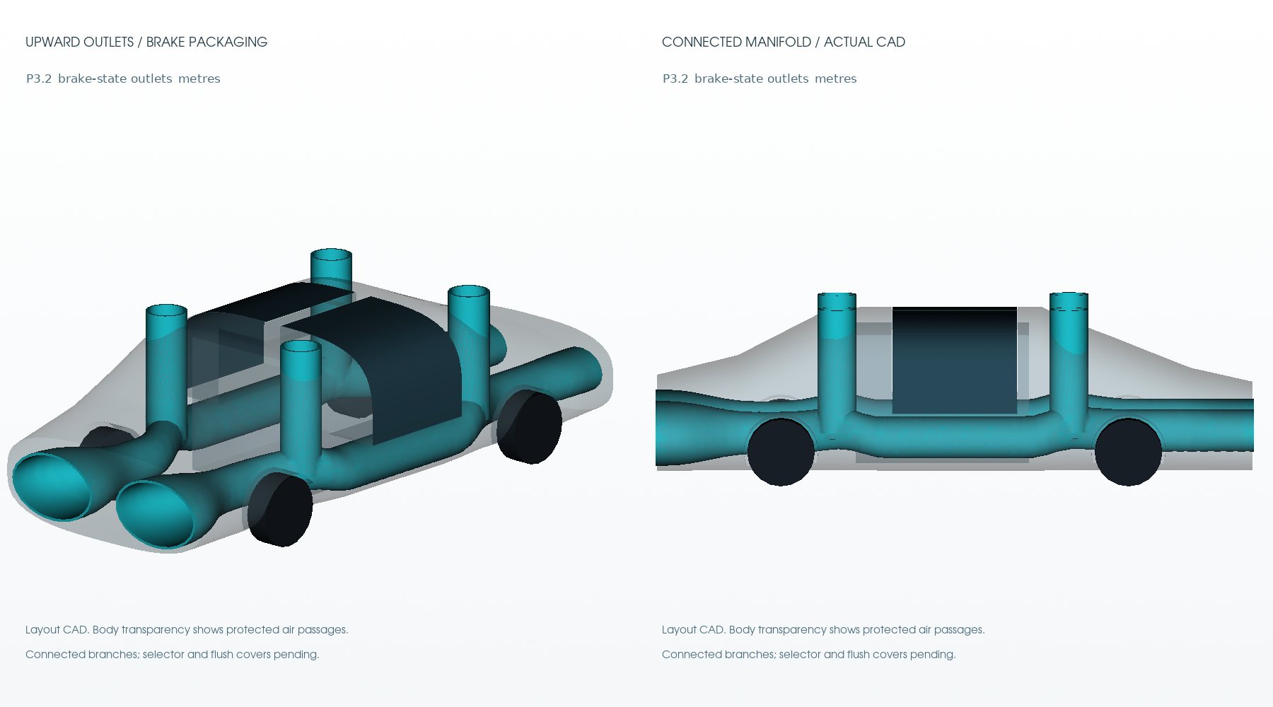
Protected duct-envelope thickness is a packaging allowance, not a qualified laminate thickness. Full-scale structural, crash, emergency-egress and dynamic wheel-clearance qualification remain ahead.
The model uses compressible mass flow, inlet and exit momentum, a lumped installed pressure loss, and a constant-area heat-addition momentum closure. The cold/heat exchanger has an assumed UA. The N₂ path accounts for each kilogram once, including useful cold service, expander work, heat demand and a reversible restoration floor.
Negative forward force is drag. The bus figure includes the assumed fan support in generator/braking mode, auxiliaries and any N₂ expander output. It excludes propulsion-engine work. Constant-speed road power is a separate external input.
Cooling a fixed, sealed gas volume lowers its pressure. Opening a flow path then admits surrounding air until the gradient relaxes. Maintaining the gradient requires continued cooling, a pressure source or another finite store. The measurable quantities are pressure, temperature, mass flow, force and heat.
Sealed chamber: p = m R T / V
Open path:     ṁ = ρ A u
Net axial F:   ṁ(uₑ cosθ − V) + Aₑ(pₑ − pₐ)cosθ
Downward F:    [ṁuₑ + Aₑ(pₑ − pₐ)]sinθ
A perfectly lossless unpowered straight duct returns zero net axial force in the limiting-case check. Useful body-shape changes must reduce the complete external-plus-internal resistance.
One stream, one rotor, one selected outlet route. Additional corner-force control and the interaction with the rear wing are not resolved by the 1D model.
The momentum equation follows NASA’s thrust equation; compressible capacity follows NASA’s mass-flow relation. Property inputs use CoolProp’s nitrogen equation of state. These sources establish the underlying relations, not the proposed vehicle’s performance.
The pressure-dependent full water cycle is retained. At the 20 MPa analytical point, roughly 0.193 kg of cycling water can charge a 307 J actuator pulse after the assumed storage loss. Charging over 120 seconds requires about 539 W of cold duty, rather than trying to complete the thermal event during the three-second door motion.
The accumulator screen gives about 87 mL gas precharge volume under the specified 80/120/200 bar polytropic reference. This is a pressure-rated component requirement, not a fabricated vessel design. Direct electro-hydraulics remains the primary actuator path.
Phase boundaries and the complete-cycle accounting use IAPWS water/ice relations. Water is reset through a melt/freeze cycle; cold and melt heat are both charged to the ledger.
The original long-range collision claim does not follow from the field model. A useful first test is narrower: two aligned 0.30 kg carts approaching at 0.10 m/s each, with cooperative 100-turn, 5 A coils of 40 mm mean radius. The filament model turns them around at about 49 mm centre separation.
Both coils dissipate about 43 W together while energised. Driver/field exchange must also be measured. A mechanical bumper remains the terminal load path. Finite winding size, alignment and current control must be tested before translating this target into real behaviour.
Circuit accounting follows mutual-inductance and field-energy relations, as explained in MIT’s inductance and magnetic-energy notes. There is no general arbitrary-object repulsion or established collision-reduction percentage.
This revision’s cryogenic resource model is for nitrogen, N₂. The earlier original conversation also mentioned nitrous oxide and nitrogen dioxide. Those have different chemistry, thermodynamic states and material requirements. No N₂ result is transferred to N₂O or NO₂, and no reactive injection power gain is credited.
A 20 bar gaseous yaw-jet store from earlier studies is another separate resource. Nitrogen that has already expanded to ambient pressure in the expander cannot simultaneously supply that high-pressure jet output.
Start with the 1:10 duct geometry and an ice-water bath. The first experiment needs no cryogenic engine or road vehicle. Compare the same installed exchanger warm and cold, at matched driving total-pressure head. Measure mass flow independently, together with temperatures, pressure loss, electrical input and bath heat.
At a 10 m/s bench stream and assumed UA of 8 W/K, the warm and cold targets are about 14.50 and 14.72 g/s. This is an instrument-sizing prediction, not data.
A one-kilogram ice inventory has about 45 minutes of ideal latent-heat capacity at this duty, before heat leaks and other loads. The bench consumes cold.
Randomise AB/BA order. Match drive head within 0.2 Pa and inlet temperature within 0.3 K. Target roughly 0.2% per-run standard flow uncertainty before other uncertainty contributions.
A separate two-axis force frame can test the upward branch. The complete duct—including its intake—must sit on the balance, so it measures the net reaction rather than exhaust force alone. Rigid feed-tube loads, flexible leads, pressure thrust and thermal-hose forces must be isolated or measured. Rotor electrical input belongs in the same record.
New, traceable composite stock for low mass; metallic hardpoints and suitable liners around motors, heat exchangers and attachments. Surface finish and joint steps become inspection requirements. No aerodynamic gain is assigned just for using carbon fibre.
Use replaceable, compliant seal sectors with wear shoes. Test candidate elastomers and engineering polymers for leakage, ice/water ingestion, wear and heat. The skirt controls pressure; ordinary premium road tyres retain grip, braking and steering.
Specify fans by their installed pressure/flow/power map, stores by usable pulse energy and current, and actuators by measured loads and response. Pressure components need their appropriate ratings and traceability. Mass targets remain open until the bill of materials closes.
| Package | Current contribution | Next evidence |
|---|---|---|
| WP1 / body and ducts | P3.1 access CAD; wider necks; P3.2 connected upward manifold. | Dynamic packaging, structural model and fresh CFD. |
| WP2 / AirDrive and heat | Coupled compressible flow, rotor modes, thermal closure and bypass comparison. | Measured K, UA, inlet recovery and rotor maps. |
| WP3 / aero braking | Pressure-envelope retests and upward air redirection. | Moving-road pressure/force measurements and valve response. |
| WP4 / trajectory braking | Prior planar studies preserved; P3 adds power priorities. | Couple the new force maps into full tyre/yaw and fault models. |
| WP5 / pulse stores | Protected 200 kJ auxiliary target; optional separate 1 MJ traction pulse. | Rated power, usable energy, isolation and thermal testing. |
| WP6 / contact and suspension | Normal rolling contact retained; body-mounted suction/skirt route. | Rough-road seal, suspension, pitch and wheel-load tests. |
| WP7 / recovery | Ram generation and finite wheel-regeneration accounting. | Converter/motor maps and repeated duty-cycle measurements. |
| WP8 / cryogenic routing | Exclusive real-N₂ path and finite cold/heat allocation. | Exchanger pinch, boil-off, pump/expander and useful-load tests. |
| WP9 / freezing pressure | Full-cycle water work and slower accumulator precharge. | Qualified pressure/phase-rate demonstrator. |
| WP10 / magnetism | Cooperative low-speed docking force target. | Finite-winding force, driver energy and alignment measurements. |
| WP11 / joint control | Reserve, interlock and resource arbitration screens. | Transient controls, perception, sector faults and hardware-in-loop. |
| WP12 / review and paper | Reproducible calculations, CAD and a falsifiable first experiment. | Real data, uncertainty review and independent replication. |
The original public braking release focused on WP3—one of twelve packages, 8.3% by count. This revision develops additional branches. Neither count is a percentage of project completion or validated performance.
The throat and outlet equations use the perfect-gas compressible mass-flow relation. The network closes a subsonic root for mass continuity. A lumped K represents form/friction losses; temperature-driven pressure changes in the heat section use constant-area mass and momentum conservation. A separate isobaric-stagnation approximation is retained as a model-form sensitivity, not a confidence interval.
Whole-car road power combines the explicitly assumed external drag area, rolling resistance and signed duct force. Ground suction uses a compressible leakage relation and an assumed installed fan map. Positive adverse ΔCp is swept; helpful negative-Cp flow receives no extrapolated benefit.
Performance retains empirical calibration errors and explicitly separates electronic/gearing limits from aerodynamic power equilibrium. Superposed reference-wing, suction and duct forces need coupled 3D validation. All underlying inputs and detailed limitations are in the downloadable JSON and Python files.
Download the source, inputs, computed results and real layout CAD. The prototype package contains the small prior-model dependency set needed to reproduce these calculations. The original P3.0 candidate remains archived locally so the rejected geometry and reserve strategies are not erased.
The Python scripts regenerate the operating points, finite-resource cycles, failure retests, performance comparisons and CAD. Input/output hashes and numerical checks are captured in the computational audit.
Read the audit · Read bench predictions · Download the 3D brake mesh
Further theoretical testing and physical measurements are to come. New results should update the model inputs and dated evidence log, including outcomes that reduce the projected benefit.