
0–100 km/h
Traction boost and airflow operating
P3.7 · The continuous performance model
Launch. Stop.
One system.
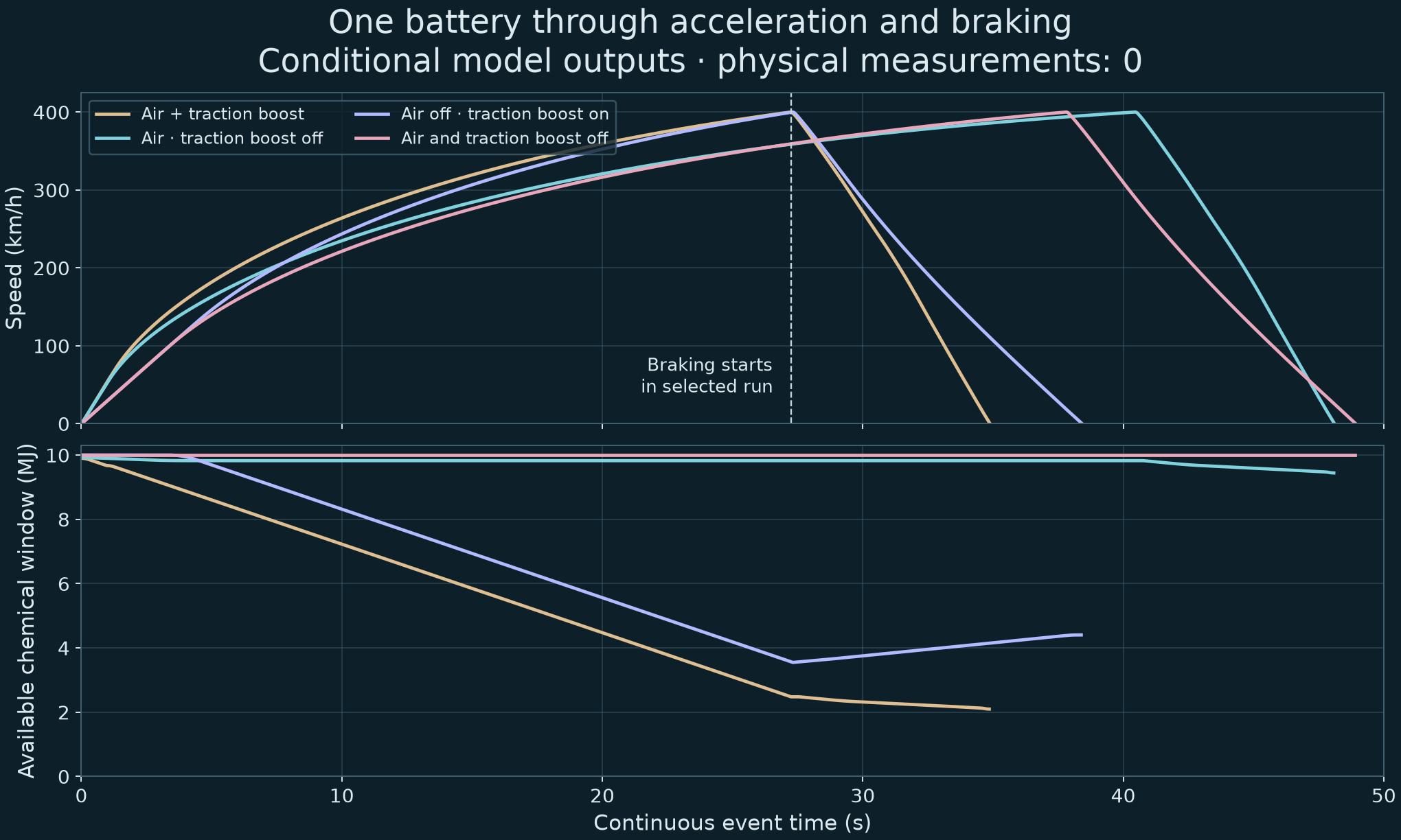
Could CryoPulse out-accelerate and out-brake a Bugatti Chiron? The next model follows the same wheels, suspension and battery through acceleration and braking.
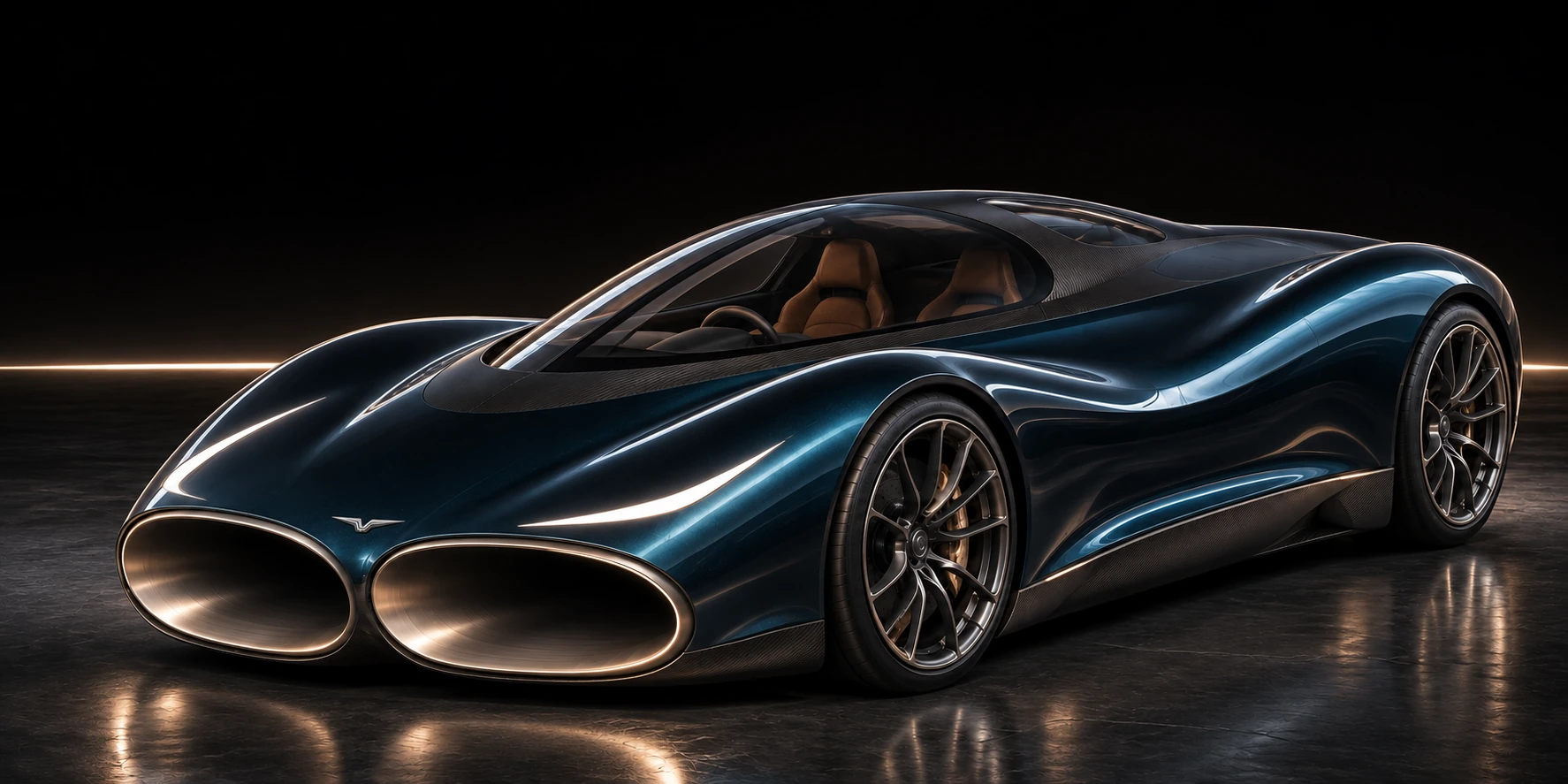
A developing hypercar concept. Further theoretical and physical testing to come.
Conditional model results. Physical measurements: 0.These figures depend on the tyre, fan, seal, battery and aerodynamic targets. They describe an unbuilt vehicle and do not establish real-car superiority.
0–400 km/h
One finite battery operating window
400–0 km/h
Immediately after acceleration
Complete 0–400–0 km/h event
No battery reset between phases
{{MASS}} kg model massSame tyre law in both phases3 mm fixed leakage-gap target217 kW shared DC ceilingZero cryogenic driving credit
01 · The car is an ecosystem
The next phase starts
where the last one ends.
Wheel speed, suspension movement, remaining energy and cell heat carry directly into the stop. No fresh battery appears at 400 km/h.
Same initial operating resources and fitted engine-power envelope.
Ready to launch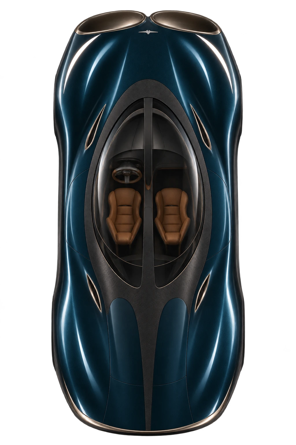
Vehicle speed0km/h
Event distance0m
Available chemical window10.00MJ
Cell temperature25.0°C
Underfloor pressure force25.0kN
Wheel slip · front / rear0 / 0%
Readouts and charts use the calculated histories. Car styling and moving arrows illustrate operating modes; they are not CFD or measured airflow. The fans are prepared before the launch clock; preparation energy and auxiliary work are debited.
02 · What the figures actually say
A faster launch target.
A shorter stop target.
The new calculation can target both. It also shows where the trade-offs remain: carrying the full system slows some engine-only acceleration intervals.
| Event | Chiron · published | CryoPulse · boost on | CryoPulse · boost off |
|---|
A benchmark to pursue.
Bugatti’s figures are published vehicle results. CryoPulse’s figures are calculations with an assumed {{MASS}} kg mass, a fitted effective engine-power curve, added electrical traction power and unmeasured component targets.
The common tyre law is a modelling improvement. Its calibration does not independently reproduce a Chiron’s launch, shifts, tyres or complete telemetry. Small numerical advantages in an individual interval are not established real-car advantages.
Bugatti’s published reference ↗And unrestricted speed?
This continuous model is checked through 400 km/h. The earlier 447 / 457 km/h screens remain separate aerodynamic targets. New duct geometry, tyre ratings, gearing, high-speed flow and thermal rejection must be qualified before revising an unrestricted-speed claim.
The fitted engine-power envelope is unchanged between CryoPulse operating modes. “Boost off” disables electrical wheel assistance; the floor fans still draw electrical energy.
Inspect the earlier speed screen ↗{{MATCHED_GAIN}}% shorter dry stop in the identical-start control.Air on: {{STOP}} m. Air off: {{MATCHED_OFF}} m. Both begin braking with identical mass, wheel speed, suspension and remaining stores. This control isolates the airflow system within the model.
| Condition | Air off | Air on | Peak lateral position · on | Peak heading · on |
|---|
Distances exclude driver reaction. A heading limit and a 3.6 m corridor are declared numerical tests. The imposed grip multipliers are not measured wet, snow or ice properties.
03 · Use the air where it helps
Different jobs.
Different airflow modes.
Launch
Powered floor suction increases tyre loading from a standing start. The selected logic briefly uses rearward airflow while traction limits wheel power, then gives the electrical margin to the wheels.
Accelerate
Floor suction tapers away between 110 and 150 km/h. This releases electrical power and reduces capture and rolling losses as the demand shifts from traction toward power.
Brake
The upper outlets redirect flow upward and rearward to add downward and braking reaction. Floor pressure adds tyre load while the wheels retain steering contact.
{{FAN_DIAGRAM}}
Five series stages across three parallel paths. This is an equivalent pressure/flow requirement map; installed full-size fans have not been selected or measured.
Give the fan bank room to work.
The earlier six-stage, two-path layout reached only about 18.9 kN in the launch screen. Five stages with three parallel paths reach the 25 kN design target at a 3 mm equivalent gap, at about 29.6 kW.
The larger layout carries a 100 kg fan-bank mass allowance, versus 40 kg in the earlier map. That added mass is included in the driving calculations. The carrier, floor structure and suspension allowances add further mass.
Open the component requirements ↗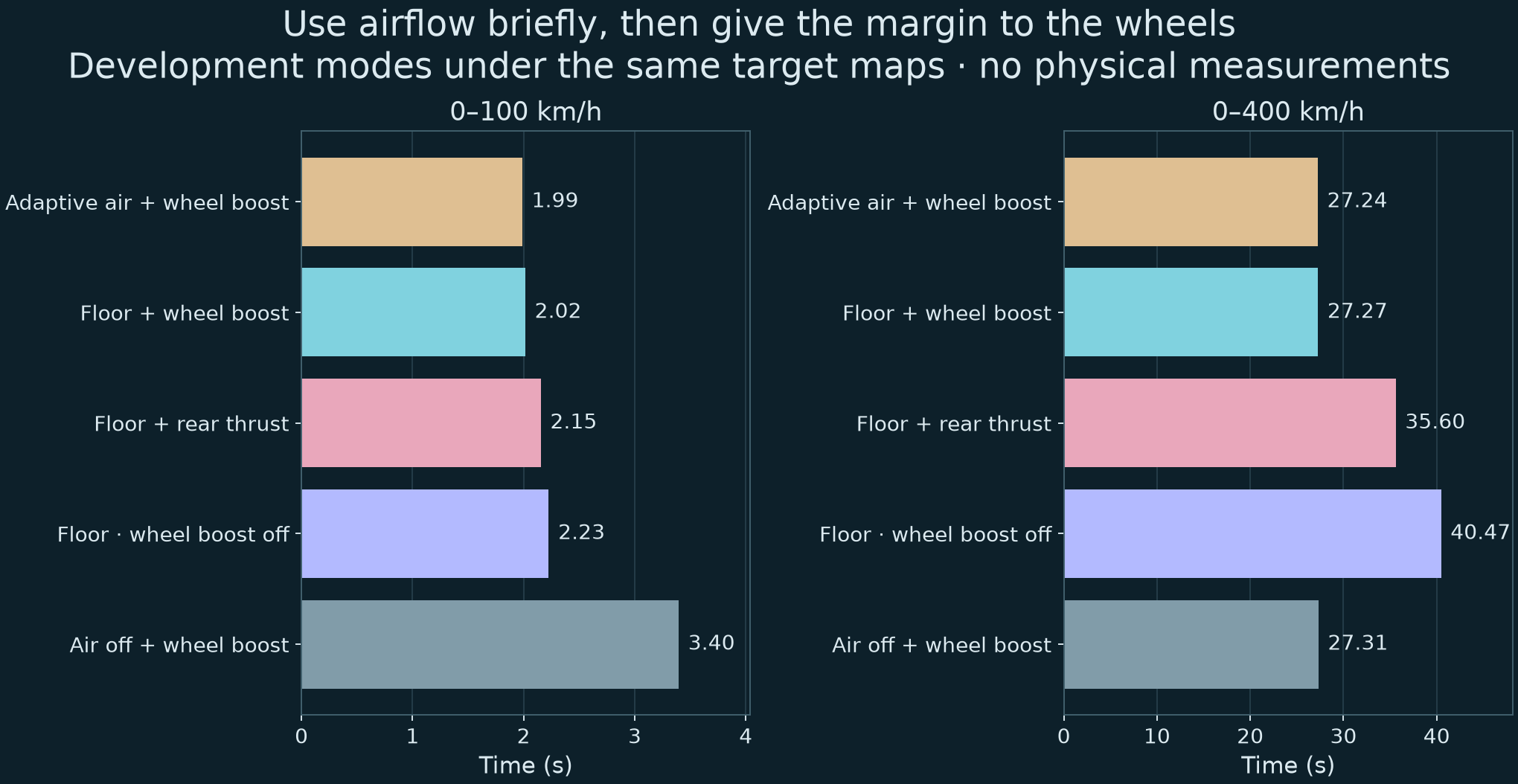
04 · One finite electrical system
Power has a limit.
Heat has a destination.
Count the whole event.
The candidate pack uses a 216-series, 10-parallel P50B cell arrangement and a {{PACK_MASS}} kg assembled-mass target. Only a declared 10 MJ chemical operating window is available to the event; the DC exchange window is capped at 8 MJ.
Terminal voltage, cell current, resistance loss, converter loss and adiabatic cell heating are calculated. The nominal cell voltage and resistance window remain qualification targets.
The source records the same physical pack before and after braking. Regenerative charging is limited by voltage, current and remaining operating capacity.
Friction braking fills the gap.
When the battery cannot accept all requested regenerative power, the controller asks the friction brakes to provide the remainder. The shared DC ceiling also covers powered airflow and actuation.
A long low-grip stress case exposed a second issue: voltage and heat losses can consume the chemical window before the DC counter reaches zero. The selected guard protects control energy and reduces fan demand through the pressure/flow map.
Inspect the failed case and the revision ↗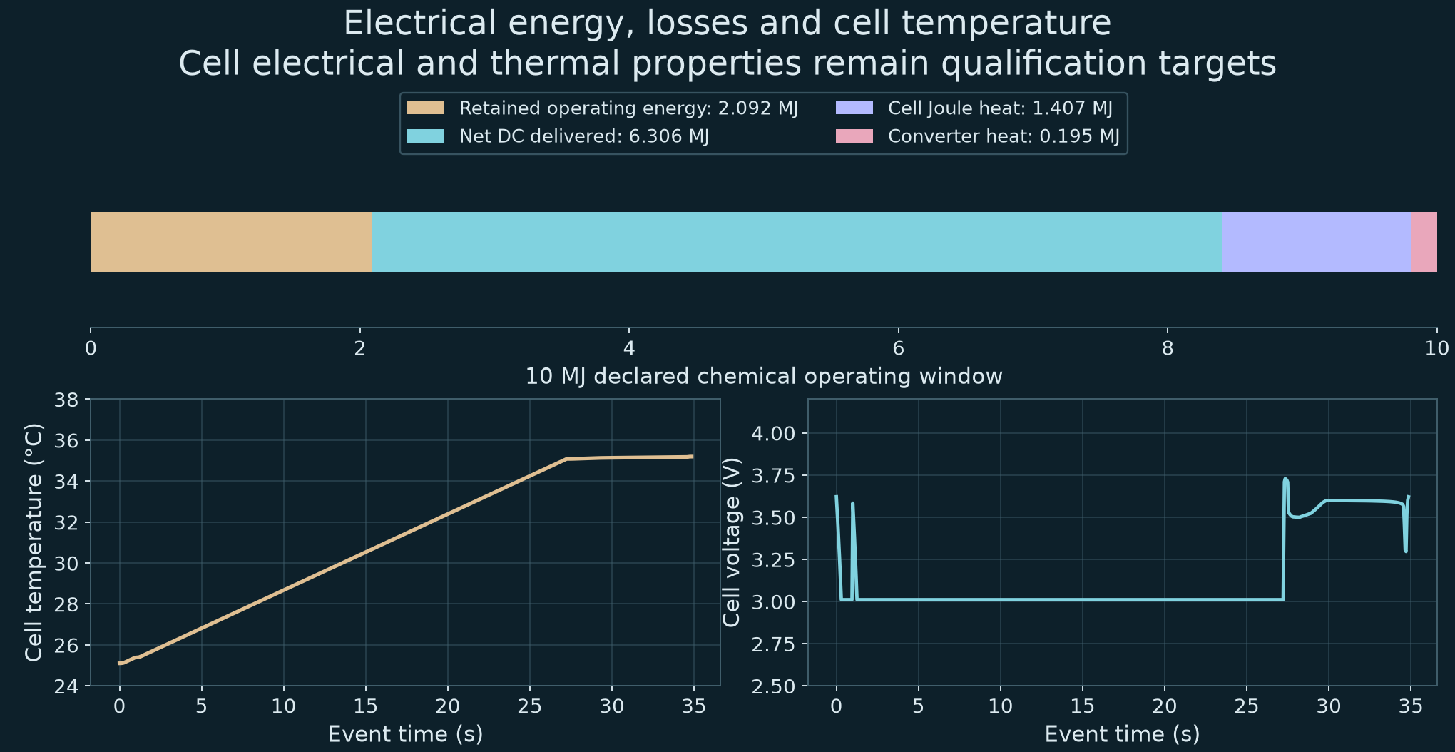
P50B published cell ratings inform the requirement screen; they do not qualify an automotive pack. Molicel’s primary cell information ↗
05 · Make the leakage-gap assumption earn its place
The body moves.
The seal must follow.
A separate carrier.
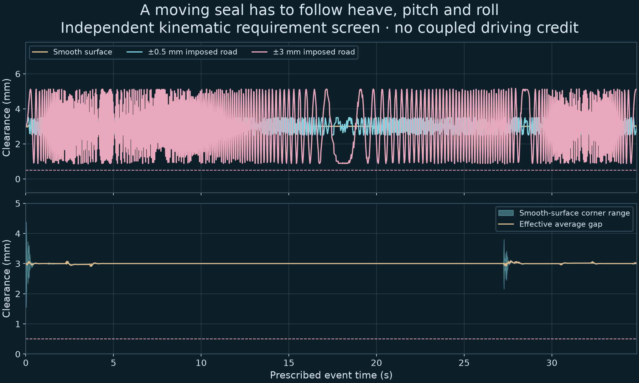
The component study uses a four-point carrier around a 2.5 × 1.2 m floor, with a 120 mm body-floor clearance target, 140 mm travel and a 0.4 m/s speed limit. Delayed height observations and movement prediction guide the carrier.
On the prescribed smooth-road event, the predicted average gap stays between {{GAP_MIN}} and {{GAP_MAX}} mm. Local corner clearance is checked separately. The actuator screen requires about {{SEAL_POWER}} kW peak, within its 1 kW target.
These are kinematic requirements. The driving results still assume a fixed 3 mm effective leakage gap. Carrier motion and cavity pressure have not yet been coupled back into the vehicle equations.
Turn the next limit into a rig.
A 3 mm imposed road ripple breaches the clearance target. The next seal rig must measure local compliance, leakage, wear and safe retraction over a moving surface before rough-road suction receives performance credit.
The finite-mass plenum study also follows pressure while cavity volume changes. Its startup lag is used to develop standby and valve requirements, rather than treating pressure as instantaneous.
06 · The shape is part of the system
Keep the flow path
inside the design.
The wheel arches matter.
The moving-ground CFD proxy includes rotating wheels and approximate contact footprints. A connectivity audit locates communication between the intended ducts and the wheel-arch cut-outs.
The next liner revision is designed to restore an enclosed route through those regions. Its static geometry is checked against the actual wheel proxies; assembly joints and fluid connectivity remain under review. New geometry requires new mesh and flow checks; old drag results cannot be relabelled as a new design.
Keep the claims separate.
{{CFD_STATUS}}
These are low-speed calculations on an engineering proxy, rather than the luxury publicity surface. They do not validate the 0.57 m² drag-area target used in the driving model, and no high-speed percentage is transferred from them.
The actual airflow record ↗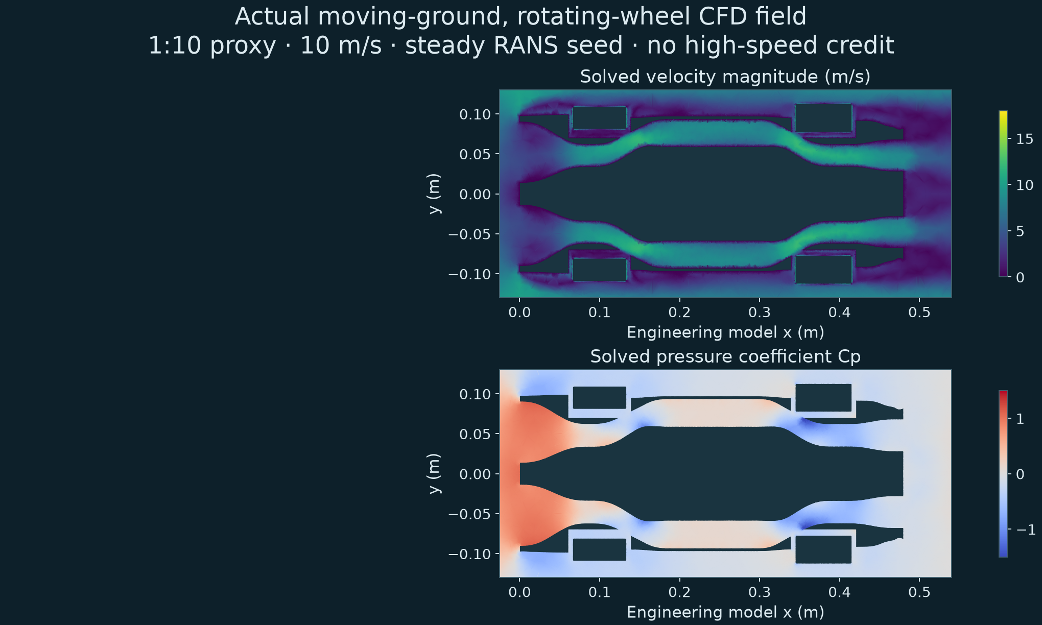
07 · The first physical proof
Build something
that can answer back.
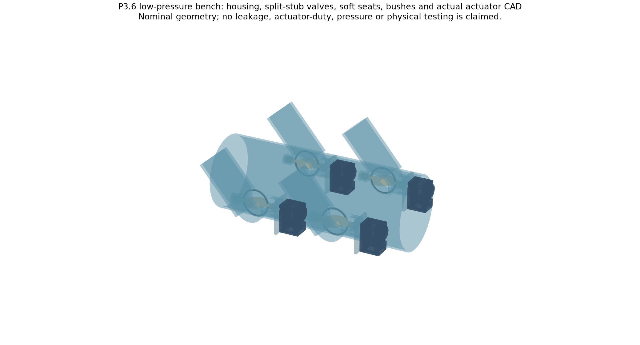
The dry-air assembly is the first proposed build: four steerable outlets, measured pressure and flow, the complete electrical input and one force balance carrying the whole blower/manifold assembly. This rig tests outlet routing; the floor needs a separate moving-seal experiment.
Measure the air.
Record installed flow and pressure in each outlet state. Check actuator travel and leakage under the actual pressure load.
Close the force balance.
Randomise outlet states, repeat independent runs and measure force with uncertainty and exit momentum. Support the complete air source on the balance.
Replace the targets.
Feed measured maps and confidence limits into the same vehicle model. Recheck the complete event and failure cases after every material change.
08 · The wider CryoPulse system
The cold branch continues.
Its resources stay visible.
CryoPulse also studies cold-induced pressure deficits, nitrogen expansion, heat exchange, pressure storage and magnetic actuation. The programme is larger than the braking study.
The latest closed resource screen prepares 6 kg of nitrogen, includes declared warm hardware and startup consumption, and calculates about 76 kJ net DC potential. The full charge’s reversible preparation lower bound is about 4.45 MJ.
Unspent liquid, residual cold gases and cooled hardware remain in the availability account. The cold hardware is a separate branch. Adding it requires its mass and demand to be rerun; it receives zero driving-energy credit in this release.
One connected programme.
Twelve work packages.
This revision connects acceleration and braking more closely. Accessible doors, cabin packaging, materials, thermal routing, phase-change actuation and cooperative magnetic docking remain part of the wider plan.
A defensible completion percentage needs defined build and measurement milestones. It cannot be inferred from the number of simulations.
09 · A reviewable scientific record
Open the model.
Challenge the assumptions.
{{REGRESSION}}guard regressions{{FRESH}}fresh combined cases{{NUMERIC_DELTA}}%largest time-step change0physical measurements
What is checked
Rotating-wheel work, suspension work, tyre dissipation, finite electrical stores, battery losses and rotor heat are audited. Closed-form limiting cases and a finer timestep check support the numerical implementation.
The first fresh batch exposed an energy failure. A finer timestep later exposed a grip estimate that latched onto an early transient. Those findings led to the energy guard and filtered estimator. Previous cases became regressions; the final fresh combinations were frozen before their runs.
What still needs evidence
Installed fan maps, tyre force and load ratings, external drag, seal following, coupled pressure response, structures, thermal gradients and control hardware remain unmeasured. Road forcing, full unsprung dynamics and tyre temperature maps are unresolved.
The calculations can guide a prototype and identify requirements. They cannot substitute for the bench, wind tunnel and instrumented vehicle.
All development modes and retained failures
Rear thrust, wheel assistance, mixed operation, fan layouts, early braking blends and the first low-grip energy failure remain available. Repeated tuning cases are counted as development or regression, rather than fresh validation.
Development record ↗Primary references and existing fan cars
Fan-assisted vehicle grip is established technology. McMurtry publishes up to 2,000 kg of downforce from standstill for Spéirling PURE. Gordon Murray Automotive describes the T.50’s fan, active diffuser and selectable aerodynamic modes. These examples support the mechanism; they do not validate CryoPulse’s layout or figures.
McMurtry’s primary specification · Gordon Murray Automotive T.50 · NASA: thrust and momentum · CoolProp: nitrogen properties.
No manufacturer endorsement or novelty claim for fan downforce is implied.
The complete calculation
Model source, frozen test plans, recorded histories, component requirements and reproducibility instructions.
Download the P3.7 source ↓Inspect the release
Open the audit and numerical inputs directly. Earlier versions remain available for comparison.
Only the beginning
The next result
should come from hardware.
Further theoretical testing and physical demonstrations are to come. The aim is a better complete car, with every gain backed by a force, energy and measurement record.