50mm
Calculated static clearance after rerouting

P3.8 · The next engineering branch
An enclosed route through the body. Room around the tyres. Cold pressure and heat recovery with their energy costs counted. The next CryoPulse takes shape from the inside.
Theoretical development · Physical measurements: 0
50mm
Calculated static clearance after rerouting
12spans
All sampled passages enclosed and connected
{{LOOP_NET}}kJ
Steady net DC, common-shaft target
{{REHEAT_NET}}kJ
Steady net DC from a separate resource screen
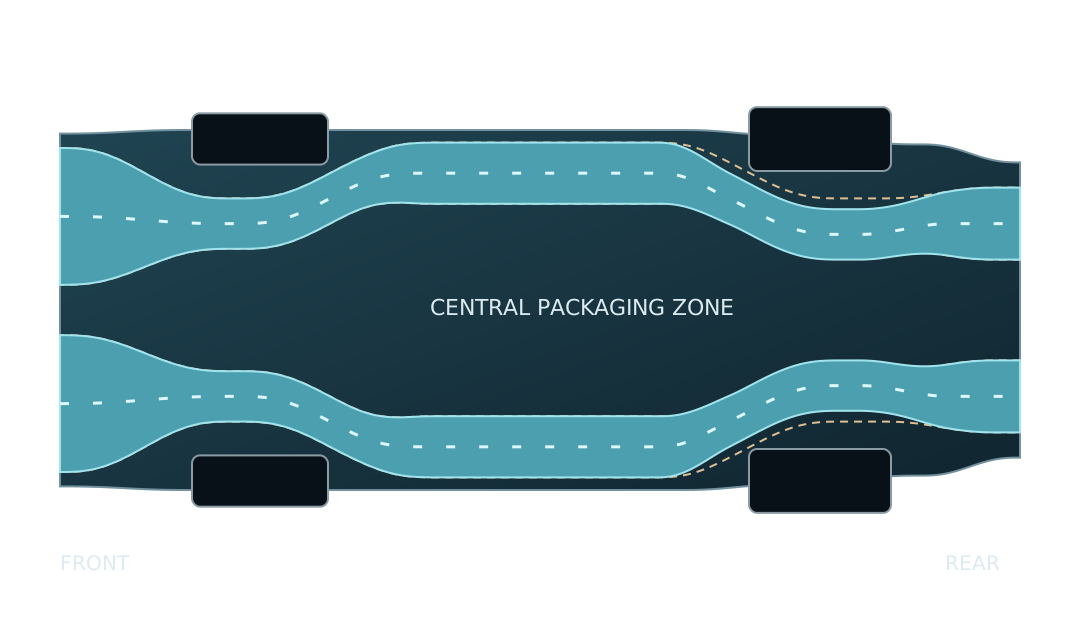
01 · A passage, not a wheel-arch shortcut
The first liner closed the intended passage, but left only 0.34 mm beside the rear tyres. That was not enough room for a usable design.
The new path moves inward by up to 60 mm near the rear axle. Its section dimensions at the design stations stay the same. Rear static clearance rises to about 50 mm; the minimum around the front wheels remains about 39 mm.
A fluid-connectivity check compares the earlier body with the revised design. The earlier duct communicates with the wheel arches. All 12 sampled spans in the revised mesh stay enclosed and connect across both axial cuts.
{{MESH_STATUS}}
Static undeformed wheel geometry. Steering, suspension travel, tyre growth, joints and wall construction still need qualification. The 20 mm outer joint envelope is geometry allowance, not a solid wall or a material-mass estimate.
02 · Returning to the original cold-pressure idea
A pressure difference can drive flow. To sustain it, the system must keep doing work and moving heat. This closed nitrogen loop cools the gas before compression, then warms it before the turbine. Under the selected targets, expansion returns more shaft work than compression requires.
Sending all turbine work through a generator and back through a motor loses part of it twice. A common shaft supplies the compressor first. Only the surplus drives the generator.
With an assumed 96% shaft transmission efficiency, the selected steady net output rises from 5.9 to 14.9 kJ. The heat source, nitrogen states and flow throughput are the same in this comparison.
Common-shaft turbine/compressor arrangements exist in industrial cryogenic machinery. Their use here still requires compact machine maps, speed matching and a startup drive.
The selected 20-second screen circulates 2 kg of working nitrogen through the machines. A separate prepared liquid-nitrogen bath boils about {{LOOP_BOIL}} kg to absorb the rejected heat.
The finite warm-side air stream contains 30 kg at 300 K. The cold vapour and unspent liquid remain in the resource account. This is thermal work from prepared cold and supplied heat.
Startup, installed mass and real pressure dynamics are not closed. Vehicle energy credit: 0.
Explore the requirements
Selected steady output is positive. Startup, machine maps and hardware remain unqualified.
Precomputed design grid: two drive layouts, four cold temperatures and five efficiency targets per machine. These are sensitivity screens, not reliability trials. Warm-air pressure-loss target: 200 Pa.
Equal turbine and compressor efficiency at steady break-even, with all other selected targets fixed.
Cold compressor inlet at break-even, with both machines at 80% efficiency and the other selected targets fixed.
Warm-air pressure loss at break-even, with all other selected targets fixed. Each limit is varied separately.
03 · A separate expansion route
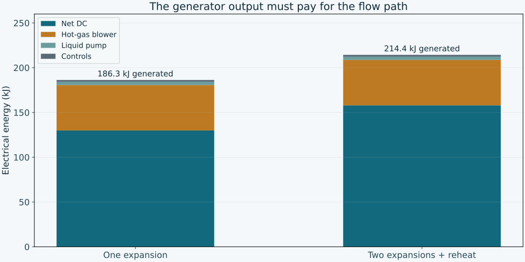
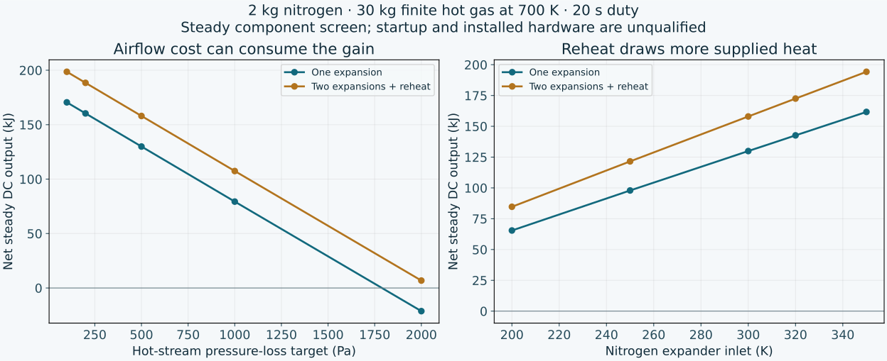
The liquid-pump branch uses a different arrangement: pump prepared liquid nitrogen, heat it, expand it, then reheat and expand again. For the selected finite resources, two-stage expansion raises steady net DC by {{REHEAT_GAIN}}%, from 129.9 to {{REHEAT_NET}} kJ.
Both layouts use a 2 kg nitrogen batch, a 30 kg generic hot-gas stream initially at 700 K and the same 500 Pa total hot-side pressure-loss target. Reheat takes more heat from that stream. It also requires a second core to meet the shared pressure-loss target.
The 6 kg prepared liquid charge has a reversible preparation lower bound of about 4.45 MJ. Four kilograms remain before startup in this steady screen. Actual preparation work is higher than its reversible lower bound.
The pressure loop and reheated expansion use different heat sources and machines. Their net outputs are separate component studies, not a ranking on equal total resources.
These steady values cannot be compared directly with P3.6’s startup-inclusive 76 kJ calculation. This new hardware still needs its own startup, materials, mass and installed-flow solution.
Finite hot stream, liquid-pump input, blower work and controls are included. No driving credit.
Inlet temperature is in kelvin; pressure loss is in pascals. Turbine efficiency target: 70%. Generator: 90%. Heat-transfer conductance and pressure loss require hardware evidence.
04 · Actual solver records
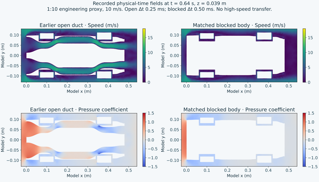
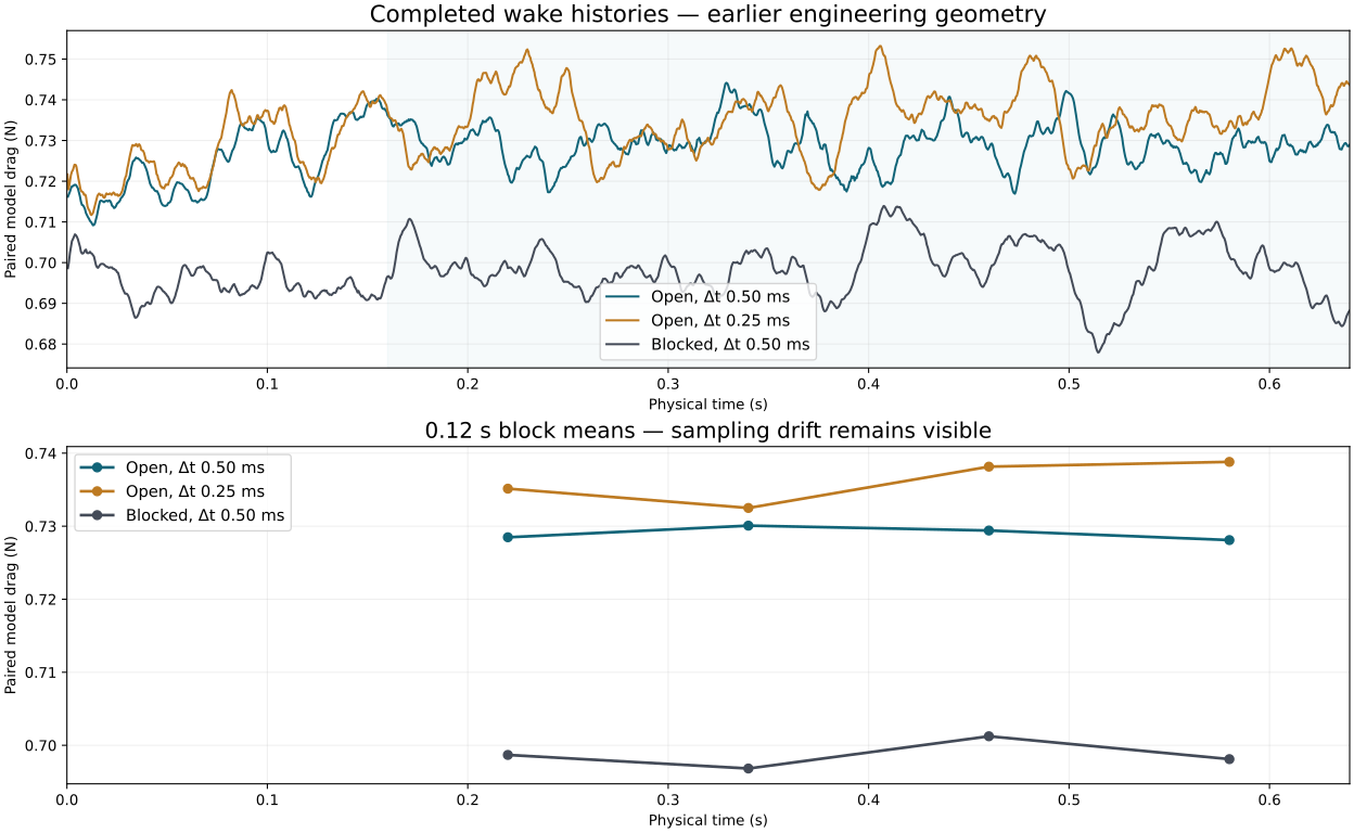
The earlier body now has completed physical-time wake records, rather than steady iterations alone. Halving the timestep changes its mean open-duct drag by {{WAKE_STEP}}% over the common 0.16–0.64 second interval.
In that short matched interval, the earlier open body has {{WAKE_DRAG}}% more drag than its blocked control. Its wheel-arch communication is one reason to rebuild and retest the passage. That result belongs to the earlier geometry.
{{MESH_STATUS}}
These are 1:10 low-speed engineering shapes at 10 m/s with moving ground and rotating wheels. High local Courant numbers, unresolved boundary layers, grid sensitivity and longer wake sampling still limit interpretation.
No low-speed percentage is transferred to the 400 km/h vehicle model.
05 · Bring the gains back to one car
Use the proposed dry-air rig for outlet flow, pressure, force and electrical input. Test the moving floor seal separately. Replace assumed fan and leakage maps with measurements.
Check the revised ducts through steering and suspension travel. Resolve joints, supports, cold/hot materials, door access and the upper outlet installation.
Add qualified mass, drag, thermal loads and energy to the same continuous launch-and-stop model. Publish new benchmarks only after that combined run passes its checks.
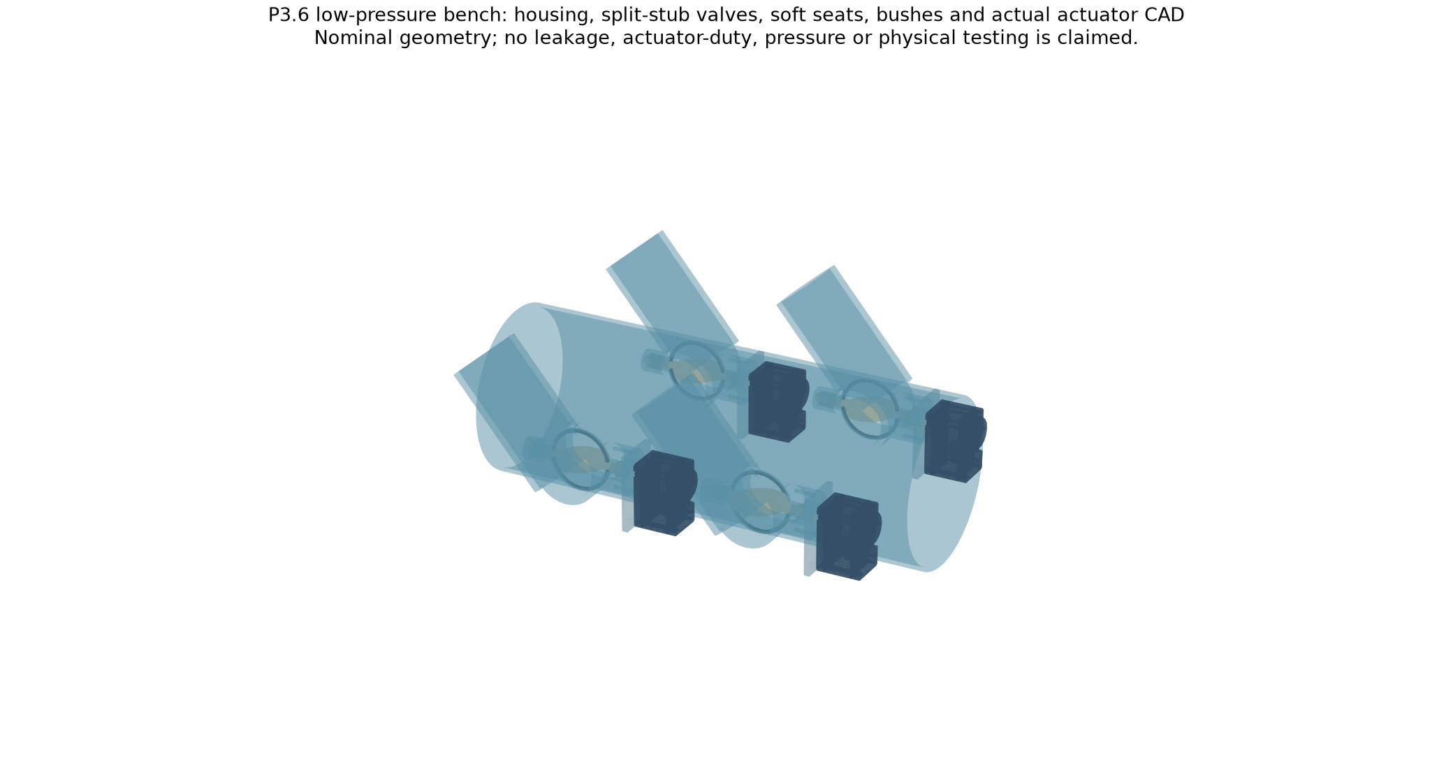
Calculation source, exact selected meshes, CAD, rejected checks, numerical records and web assets.
Download the development source ↓The vehicle source stays fixed. New component work remains separate from the driving benchmark.
All 200 pressure-loop states, 40 recuperator states and 50 reheated-expansion states close their declared energy and exergy identities. Zero turbine and zero generator controls consume net electricity, as expected. These are numerical consistency checks, not measured performance.
Warm expansion supplies turbine shaft work. Cold compression consumes shaft work. The common shaft supplies the compressor first; the generator receives the surplus.
The selected recuperated point gives about 80.5 kJ turbine work and 52.6 kJ compressor work. After the assumed shaft and generator losses, 23.2 kJ reaches DC. Warm-air flow and controls consume about 5.0 kJ, leaving 18.2 kJ steady net output.
The availability account also retains unspent liquid, cold vapour and bypassed air. The selected used-resource availability is about 269.4 kJ; 18.2 kJ becomes net DC and about 251.2 kJ is destroyed through irreversible processes. The independent entropy calculation gives the same destruction through T₀Sɡₑₙ. This is a consistency demonstration of the declared model, not a measured device.
Nitrogen properties use the CoolProp real-fluid equation of state. Geometry and meshing use Gmsh; flow uses OpenFOAM v2412. Cryostar describes industrial common-shaft expander/compressor arrangements, and Air Liquide describes industrial cryogenic turboexpanders. These establish existing mechanisms, not compact CryoPulse part ratings or endorsement.
The cold loop needs prepared nitrogen, heat transfer and compression. It makes no claim of negative energy, a self-sustaining vacuum or energy creation. None of the new cold results supplies driving energy in the current vehicle model.