__STROKE__ mm
Calculated adjustment span for the illustrative upper link. The complete steering link, caster and driveshaft layout remain to be designed.

P3.9 / CHASSIS & AIRFLOW
Tilt the wheel with purpose. Route the air around its movement. Give each actuator a job—and an energy budget.
We are developing motorised suspension geometry alongside the braking airflow system. This chapter shows the mechanism, the packaging revision and what the reverse-thrust calculations actually change.
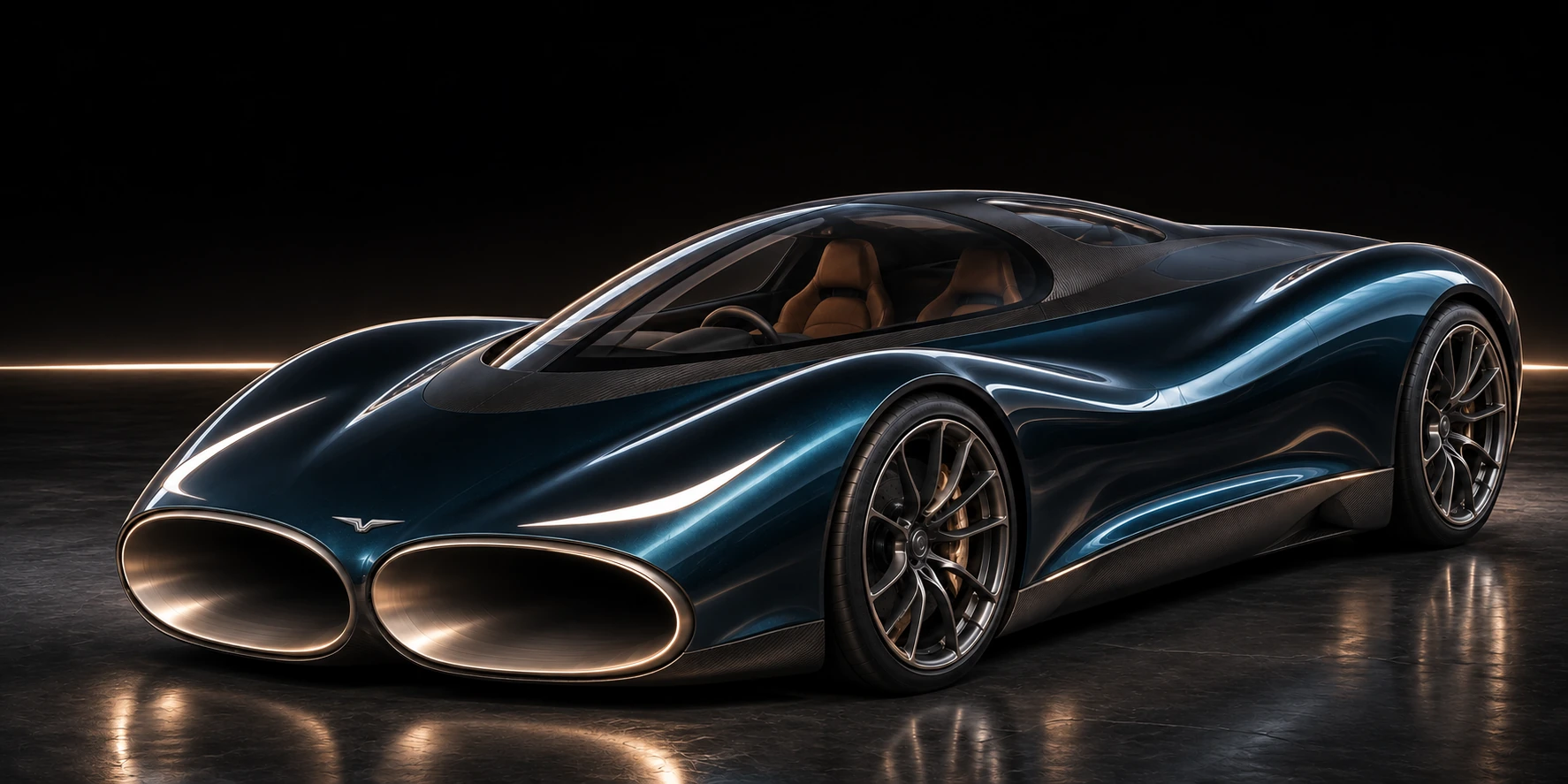
THE WHEEL / CONTROLLED ARTICULATION
An adjustable upper link changes wheel camber: the tilt seen from the front. The lower arm locates the wheel while it travels. The aim is to manage tyre contact as load and body roll change. Steering toe must be controlled separately in the full three-dimensional design.
Live front-projection kinematics. Drawn at the calculated angle. This does not simulate tyre deformation or prove constant toe.
Start with a small tilt range: −4° to +1°, across ±85 mm of wheel travel. A dedicated actuator and captured joints create repeatable movement.
Inspect all 1,785 geometry poses ↗Calculated adjustment span for the illustrative upper link. The complete steering link, caster and driveshaft layout remain to be designed.
Peak target DC draw at the selected load and 10°/s tilt rate. It includes assumed screw, motor and inverter losses. Holding and transient requirements remain open.
Actuator force before design factors, using an assumed 6 kNm resisting camber moment. It is a component sizing requirement, not a measured wheel load.
Active camber is an established engineering topic. Marelli describes an active-camber actuator; SAE research reports tyre-force tests at large camber. Neither source establishes a CryoPulse grip gain.
THE BODY / MAKE ROOM FOR THE MOTION
Adding camber changed the wheel envelope. The earlier body had __OLD_CONTACTS__ contacts in 96 sampled combined poses. We enlarged the wheelhouses, then shifted the passages inward around both axles.
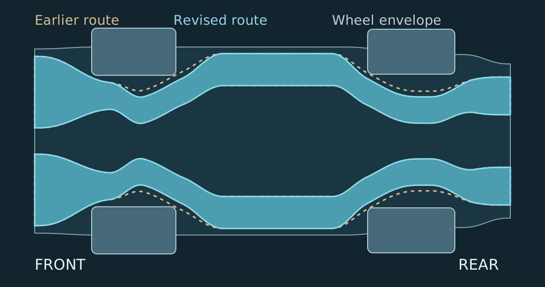
Sampled camber, vertical travel and front steering up to ±8°. The wheel’s track movement comes from the front-projection mechanism.
Minimum body clearance in the revised sampled poses. The service-clearance target is 15 mm. Continuous swept volumes and real suspension parts still require checks.
Enclosed and connected in the mesh-based topology check. Force-qualified airflow and the drag effect of this new body remain unmeasured.
The doorway station range is retained. Interior trim, hinge hardware, people, tyre deformation and suspension component clearances need their own packaging checks. The earlier P3.8 passive-flow case recorded a 6.8% drag penalty in a low-speed proxy; this new CAD result does not remove that penalty by itself. Repair of the new solver mesh continues before airflow forces can be assigned.
THE AIR / REVERSE THRUST & DOWNFORCE
Air expelled forward pushes the car backward. Air expelled upward pushes it down, helping the tyres transmit braking force. The existing 130° reaction angle already combines both effects. We tested the trade with the same launch state, mass, battery, fan power and brake model.
Directions only; arrows are not a CFD solution or a force scale. The model also includes inlet capture momentum and pressure reaction.
Forward/upward exhaust. Backward/downward reaction.
Each run begins at 130° and moves toward the selected angle at the existing assumed rate. Actuator energy comes from the same finite electrical system.
The low-grip case uses the original model’s 0.2 grip multiplier. It is not a measured ice or snow result. Configurations above 160° are symmetric exploratory cases.
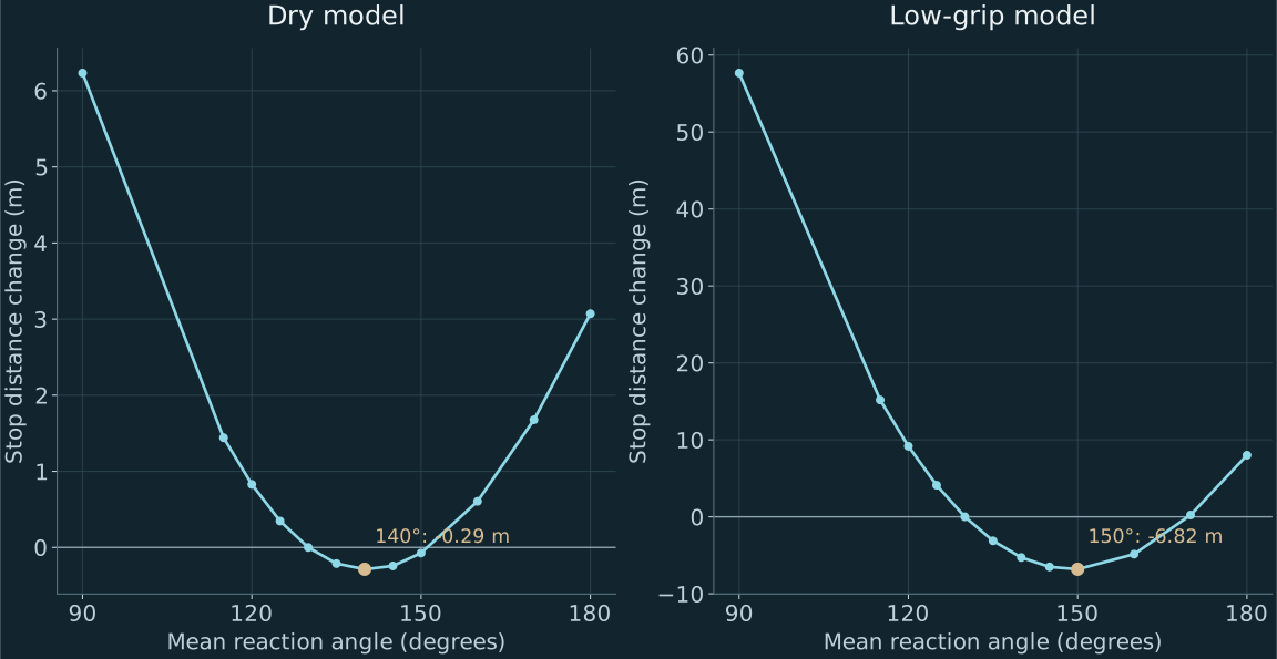
The shortest sampled fixed-angle cases are __DRY_BEST__° on dry grip and __LOW_BEST__° on low grip. Full reverse thrust sacrifices downforce and performs worse than the existing setting in these two cases. The dry improvement is only __DRY_GAIN__ m; this study does not justify raising the public vehicle headline.
The adaptive force-based controller passed the declared trajectory and resource checks in __VALIDATION__ additional runs. Its dry stop was __ADAPTIVE_DRY__ m, so it still needs a better objective before replacing the original controller.
THE MATERIAL / CHOOSE IT FOR THE JOB
Start with a high-speed radial tyre specified for the actual loads. Compare a dry-performance compound with a wet/cold specification at controlled pressure and temperature. Grip comes from the complete tyre and road interaction.
A motorcycle’s rounded profile supports large lean angles. A wide car tyre needs its own camber map; copying the motorcycle angle is not a tyre design.
Michelin: tyre construction ↗A sealed spherical bearing with a qualified PTFE-based liner is a candidate for the adjustable link. Tuned elastomer or hydraulic bushes can remain where controlled compliance improves isolation.
Joint clearance, sealing, temperature, wear and noise must be measured. Uncontrolled bush movement can also change steering toe.
SKF: spherical bearing reference ↗Use inspectable aluminium or steel for the first geometry rig. Select vehicle arms and uprights after load and fatigue analysis; forged aluminium, steel and titanium remain candidates.
Cold-loop metals stay in their own thermal design. The chassis calculation does not credit cryogenic cooling with better tyre grip.
Cold-loop material study ↗THE DEMONSTRATION / TWO STAGES
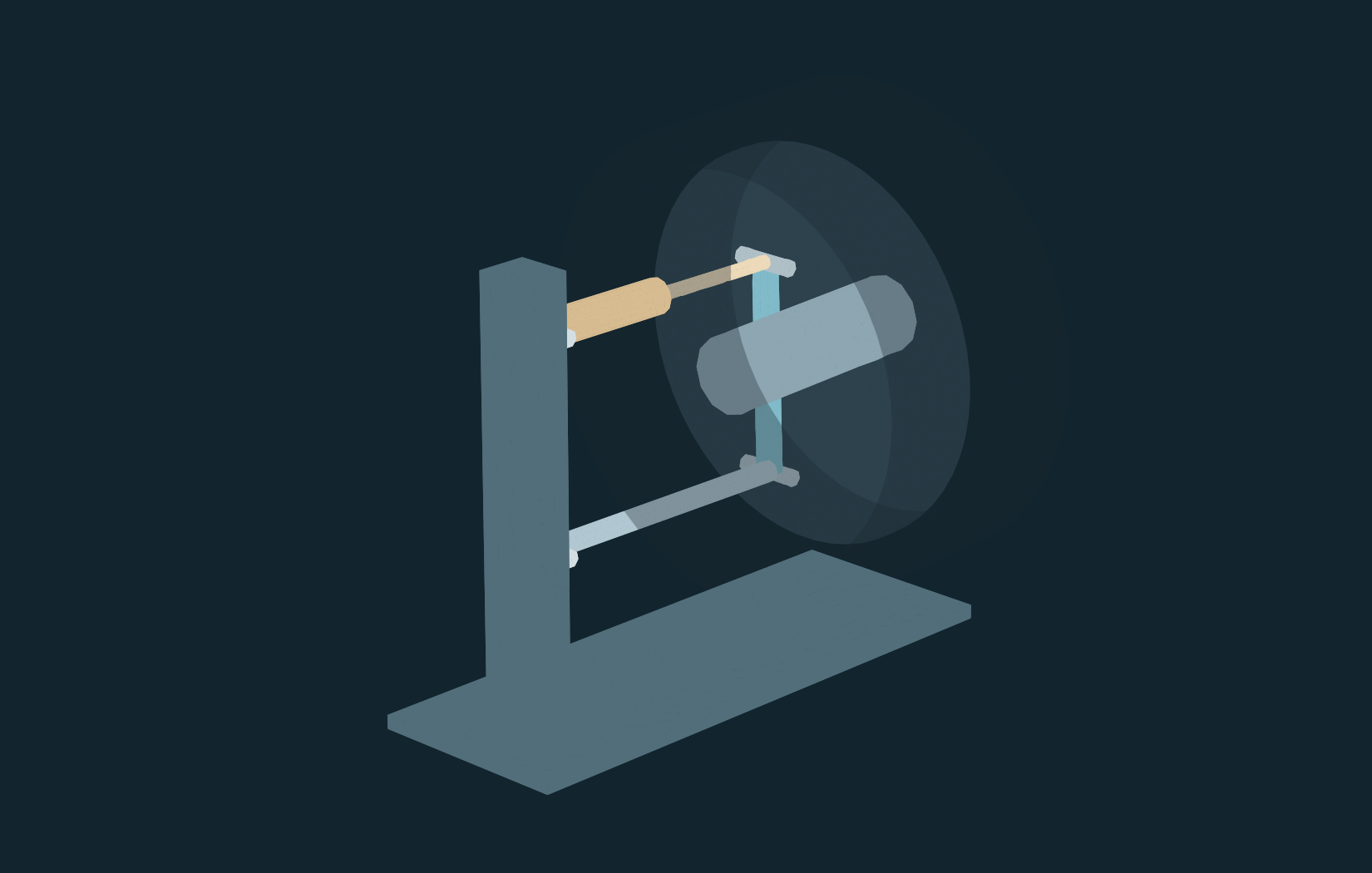
A half-scale front-view rig with a low-force actuator, captured joints, position encoders and an alignment target. Measure requested camber against achieved camber, link stroke, repeatability and interference.
This proves the mechanism’s movement. Half-scale motion does not establish full-size tyre grip.
A full-size tyre facility compares fixed alignment and active camber with the same tyre, then repeats with an alternative compound. Record longitudinal, lateral and vertical forces, toe, camber, slip, pressure, temperature and water depth.
Randomise paired repeats. Report uncertainty and test the selected control law on conditions left out of development.
THE RECORD / REPRODUCE & REVIEW
The original vehicle benchmark stays frozen. This development branch records the added mechanism and airflow-direction study separately, including the earlier clearance contacts and the controller that did not improve the dry stop.
__TOTAL_RUNS__ driving calculations, 1,785 front-projection geometry poses and __POSES__ revised rigid CAD poses. These are computational checks. Physical measurements: 0. No new active-camber vehicle performance, high-speed drag or cryogenic propulsion gain is claimed.