__CASES__ ROAD / FAULT CASES
Control through the stop.
Dry and low grip, unequal left/right grip, wind, port loss and upper-motor loss. Each run checks lane position, heading, suspension travel and finite resources.

P4 / SYSTEM INTEGRATION
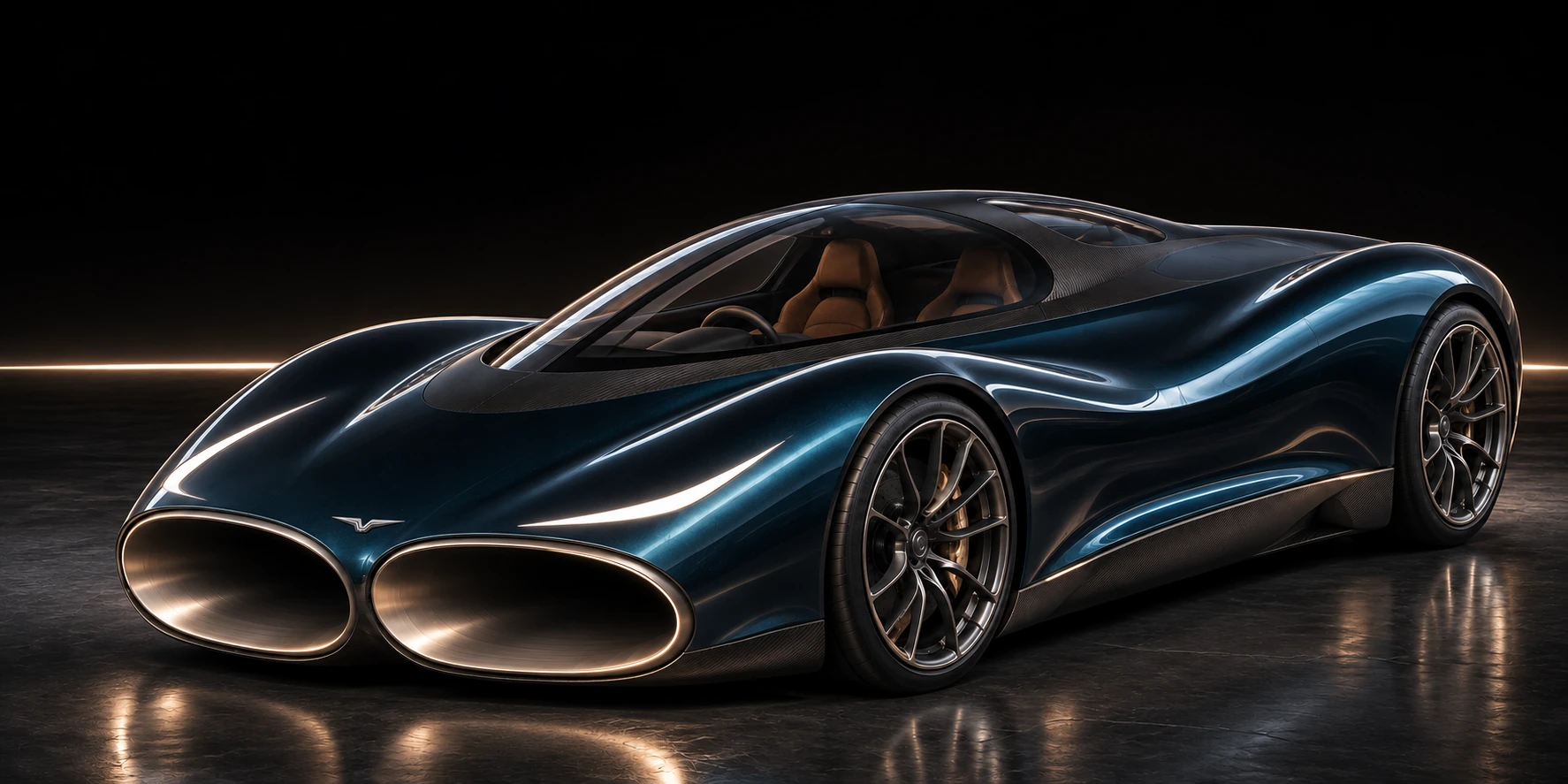
The ducts, fans, wheels, brakes and energy stores share one vehicle. This revision brings their mass, motion and power demand into the same acceleration–braking event.
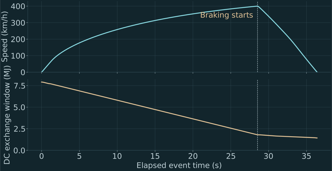
THE CONTINUOUS EVENT
No fresh battery at the braking point. Wheel speed, suspension motion, pack temperature, stored energy and cold resources carry through the event.
__RESULT_DETAIL__
__CASES__ ROAD / FAULT CASES
Dry and low grip, unequal left/right grip, wind, port loss and upper-motor loss. Each run checks lane position, heading, suspension travel and finite resources.
TIMESTEP CHECK
__STEP_DETAIL__
ENERGY ACCOUNTING
Cell heating, converter loss, actuator draw, tyre slip and friction-brake work remain in the ledgers. The cold loop receives an explicit prepared coolant supply.
CONTROLLED CAMBER / A DEFINED LOAD PATH
A dedicated hydraulic circuit adjusts the upper wishbone's inboard carriage. A separate commanded link corrects toe. The wheel-brake hydraulic circuit stays independent.
A projection of the sampled 3D linkage. Steering and shaft readouts come from the spatial solution. This drawing is not a stress analysis.
891 SPATIAL POSES
±85 mm heave, −4° to +1° camber and ±8° toe. Fixed arm lengths, upright geometry, wheel height and spindle orientation close to numerical precision.
Required carriage travel: 26.6 mm. Required steering-link travel: 43.7 mm.
15 MPa WORKING SUPPLY
The stated 6 kNm camber and 600 Nm steering loads require at most 12.49 MPa. A 30 MPa component rating gives a calculated force margin above 2.4.
The simultaneous motion test stays within 35 L/min and the 20 kW motor limit. Peak pump draw is charged while moving.
SAMPLED PACKAGING
__CLEARANCE_DETAIL__
These are rigid component envelopes. Detailed joints, hoses, tyre growth, compliance and manufactured-part strength remain qualification work.
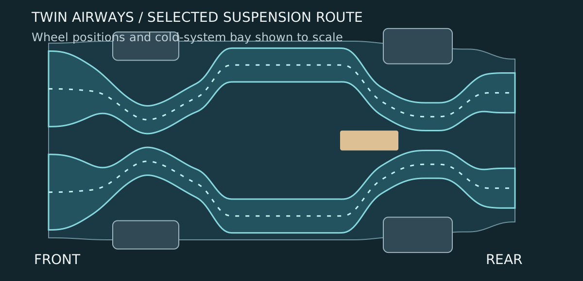
AIR THROUGH THE VEHICLE
The revised ducts move inward around the suspension mounts and carriage guides. The door area remains between the 1.9 m and 2.9 m stations.
FINITE COLD RESOURCES
The pressure loop uses stored cold and heat from warmer air. The calculation tracks the coolant consumed before driving and throughout the event.
PRECOOLING MODEL
The specified metal masses and heat-transfer targets need __COOL_S__ s of regulated precooling. The model removes __COOL_KJ__ kJ and consumes __PREP_KG__ kg of the initial 6 kg coolant supply.
SAME EVENT
__COLD_EVENT__ No coolant-boiloff mass reduction is credited to acceleration or braking.
EXTERNAL ENERGY INPUT
The reversible preparation floor for 6 kg of liquid nitrogen is 4.45 MJ; practical preparation needs more. The loop's heat exchangers, efficiencies and machine maps remain design requirements.
OPEN CALCULATIONS / CONTINUING DEVELOPMENT
This is one stage of a larger CryoPulse programme. Earlier releases remain available with their original assumptions. New body forces and new component models receive their own records.
A theoretical prototype and a test programme. No physical vehicle, tyre-force, high-speed airflow or cryogenic performance measurement has been made.