Turn the cold-and-heat idea into a testable cycle.
The original 12 work packages remain intact. P2's through-flow body, charging/propulsion/braking modes, wheel-fans, base contact and independent electromagnetic hydraulics remain in the architecture. This refinement develops the cold/heat mechanism that was previously only a supporting branch.
Evidence: theory, numerical controls and layout CAD. Nothing here is a physical measurement, proof of new energy, completed cryogenic test or validated vehicle performance. The moderate-temperature prototype isolates one mechanism before true cryogenic integration.
What “an empty area pulls back” can mean physically
A colder, temporarily isolated gas chamber can fall below surrounding pressure. Gas then enters because the surrounding higher pressure drives it. The space is not necessarily empty: the pressure deficit can be caused by cooling the gas already there. Condensation can also remove molecules from the gas phase. These are distinct, measurable mechanisms.
p V = m R T
At fixed mass and volume: p₂ / p₁ = T₂ / T₁
Flow is driven by a pressure gradient; “negative pressure” here means p − pambient < 0.
Absolute gas pressure remains positive.
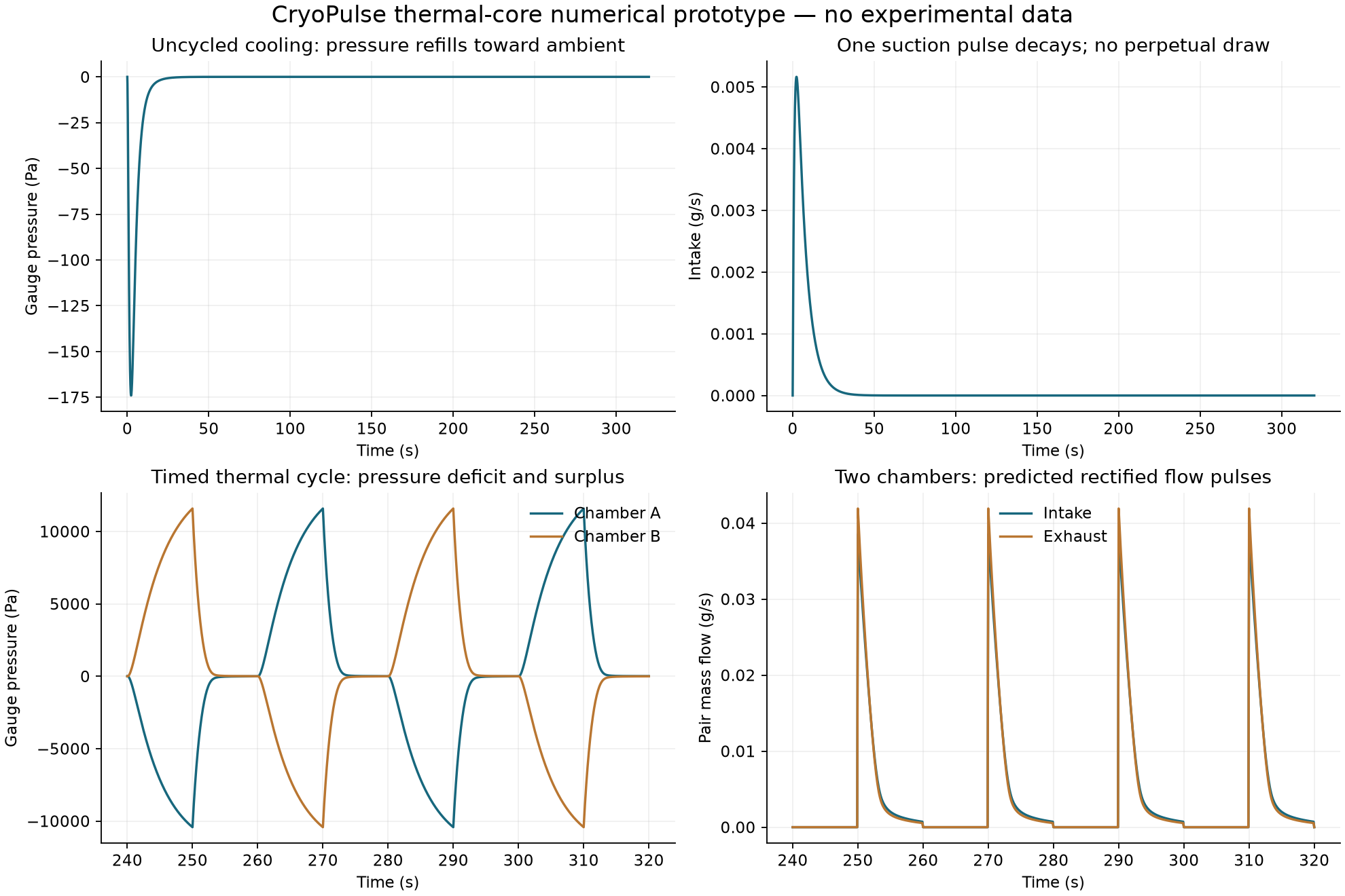
For a sealed dry-air sample initially at 20 °C and atmospheric pressure, ideal cooling to 0 °C predicts about a 6.9 kPa pressure decrease. Opening it causes a finite refill. Keeping it cold after equilibrium does not keep creating empty volume.
Basis: NASA gas relations and thermodynamics. The number is our ideal-gas calculation, not a measurement.
Energy does not have a universal preference for a negative value
The zero of energy is a reference choice. At fixed temperature and pressure, equilibrium can minimize Gibbs free energy under the applicable constraints; this is not a rule that total energy becomes negative or is created by a void. A cold store can have less internal energy than its surroundings while retaining positive available work, called exergy.
Cold-store exergy for constant heat capacity C:
B = C [(T − T₀) − T₀ ln(T/T₀)]
For T < T₀, B > 0. Warming the store consumes this availability.

Minimum work to remove heat Qc at Tc and reject it at ambient T₀:
Wreset,min = Qc (T₀/Tc − 1)
Sources: MIT equilibrium/free energy; CERN refrigeration and exergy (search-index excerpt available; the full file was access-limited during this work).
Mass, energy, entropy and flow equations used
dm/dt = ṁin − ṁout
dUgas/dt = ṁin cp Tin − ṁout cp Tgas + Hgas (Twall − Tgas)
Cwall dTwall/dt = Qhot − Qcold + Qambient − Hgas (Twall − Tgas)

The downstream/upstream expander reduces flow enthalpy by its shaft work.
Its work is counted once in the complete control-volume ledger.

Compressible orifice flow uses upstream pressure/temperature and pressure ratio.
It includes the sonic choking limit; a 1 Pa low-head regularization represents
unmeasured viscous behavior. All flow coefficients require calibration.

For the complete gas/wall/expander system:
ΔE = Hin − Hexhaust + Qhot − Qcold + Qambient − Wshaft
ΔS = Sin − Sexhaust + Qhot/Th − Qcold/Tc + Qambient/T₀ + Sgenerated
Sgenerated ≥ 0; energy and exergy residuals must close.
The uniform-volume approximation neglects pressure waves, resolved fins, spatial gradients and 3-D duct momentum. It tests thermal causality and resource accounting; it cannot establish whole-vehicle drag, thrust or downforce.
NASA compressible-flow equations; the valve regularization and lumped heat transfer are our modelling choices.
Condensation, actual cryopumping and thermal transpiration
Condensation removes gas-phase molecules and releases latent heat to the cold surface. Its pressure benefit depends on species, partial pressure, temperature and captured mass. In the separate sealed-air equilibrium calculation, initially saturated 20 °C air cooled to about 0 °C gains roughly 1.57 kPa of extra pressure reduction from water condensation beyond the same-mixture sensible-cooling result. This is not bulk-air condensation and does not include latent load, frost or continuous flow.
Actual cryopumping uses sufficiently cold surfaces to capture particular gases and requires finite capture capacity and regeneration. A 77 K nitrogen source is not permission to treat every air component as disappearing. Nitrogen, nitrous oxide and nitrogen dioxide are different fluids.
Thermal transpiration is another temperature-driven pumping mechanism, but it requires the appropriate rarefied/microchannel regime. It is not silently credited to a centimetre-scale road-air duct. Thermoacoustic pressure oscillations are a separate possible research route requiring phase, onset and loss modelling.
Primary references: NIST/IAPWS water properties, CERN cryopumps (indexed excerpt; full file access-limited), NASA/JPL thermal-transpiration pump, NASA thermoacoustic thermal management.
The revised component prototype
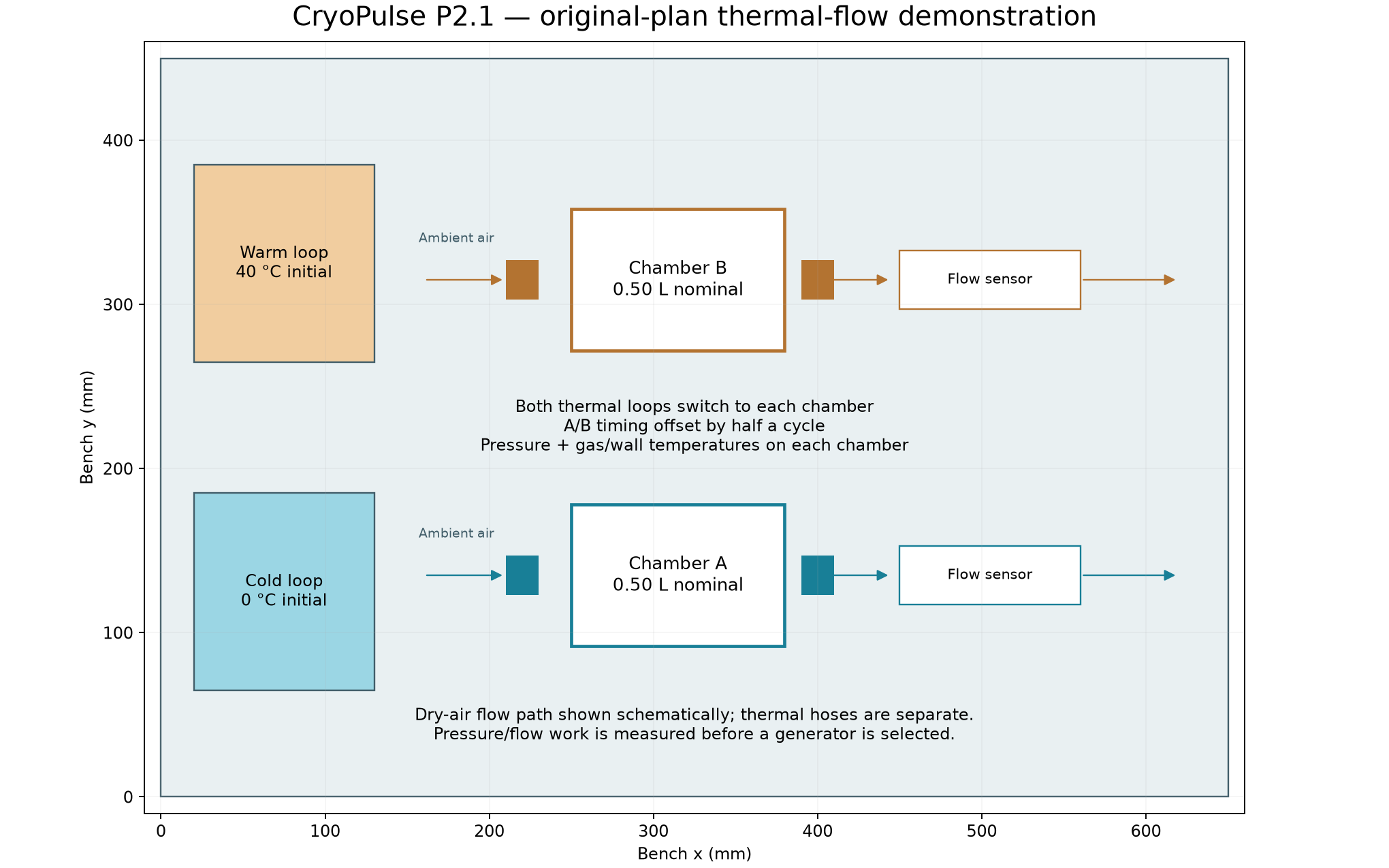
Two nominal 0.50 L chambers, separate metered thermal loops, directional valves and pressure/flow/load instrumentation. The first test uses dry air, a 0 °C cold loop and a 40 °C warm loop. These temperatures make the thermal mechanism accessible; they do not constitute a cryogenic demonstration.
Four-state sequence
Why this is a refinement
Immediate refill can erase the pressure difference before useful work is taken. Timed valves preserve a larger head; a controlled load uses that head on admission and exhaust. The chambers run half a cycle apart, which changes the pulse pattern. They do not create extra energy by being paired.
Separate hot/cold exchangers and regeneration are the next thermal-mass improvements. Their benefit is not assumed in the transient chamber model.
The STEP is a commercial-component space claim, not certified pressure-vessel or rotor fabrication geometry. The external bench is not claimed to fit inside P2's central reserved space. New 6061 support parts, copper thermal inserts and selected PEEK isolation continue the material policy; actual effective thermal mass and heat transfer must be measured.
Physical test that can establish the mechanism
The nominal shaft output is only milliwatts. A heat-duty meter with uncertainty of several percent cannot resolve that output by calorimetric subtraction. Direct work measurement and a propagated uncertainty budget are required; no unexplained heat-balance residual will be labelled new energy.
- Calibrate pressure, temperature, signed flow, heat and load measurements. Identify thermal conductance, effective wall heat capacity and valve leakage from separate transients.
- Run an equal-temperature null, sealed cooling and uncycled refill. Check pressure-temperature scaling and whether flow decays after refill.
- Run the four controlled cycle/load combinations in randomized order, with independent repeats and matched initial/final stores. Compare periodic mass throughput and delivered work.
- Measure all valve/pump/refrigerator DC energy. A pressure-flow integral estimates available pneumatic work; it is not automatically electrical generator output.
- Only then add humidity/condensation or a separately isolated cryogenic source. Measure collected mass, latent heat, cold depletion and regeneration. Actual cryogenic hardware requires fluid-specific component selection and laboratory controls.
The initial warm loop has a separate 45 °C hardware trip. Use supplier-rated pressure/vacuum components and relief provisions. No sealed freezing-water vessel or vehicle-speed deployment test is part of this bench design.
What the numerical prototype currently shows
| Control case | Pair intake mg/s | Gross shaft mW | Minimum cold reset mW |
|---|---|---|---|
| original-pressure-load | 3.656 | 0.908 | 362.2 |
| head-recovery-only | 3.793 | 0.849 | 362.7 |
| timing-only | 3.582 | 0.890 | 356.8 |
| timed-head-recovery | 3.703 | 11.740 | 355.8 |
| ambient-cold-reference | 1.747 | 2.647 | 0.0 |
At the same geometry, warm-source temperature, cycle period and model coefficients, cooling the cold side from 20 °C to 0 °C predicts about 2.12 times the intake and 4.43 times the gross shaft work. The heat duties differ. This is not a matched-total-input efficiency gain.
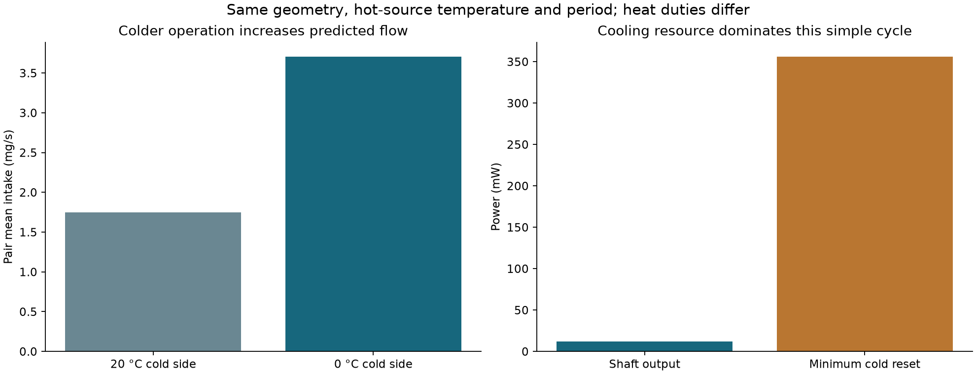
The refined 1 L pair predicts about 3.70 mg/s intake and 11.7 mW shaft output in this conditional case. Maintaining the cold source requires at least 356 mW of refrigeration work at the reversible limit, before real losses. This simple cycle therefore does not demonstrate self-powered cooling. No valve/pump overhead or generator output has been measured.
A useful component demonstration can establish a repeatable pressure/flow effect without establishing a useful vehicle power source. This model is one candidate implementation, not a universal upper limit on CryoPulse.
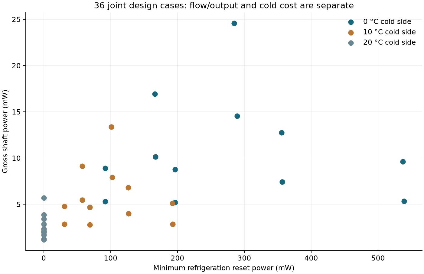
Explore the 36 joint design cases
These are precomputed input sensitivities. Heat capacities, conductances, 60% expander efficiency and pressure-head sharing are assumed. They are not hardware ratings or an optimized manufacturable design. Displayed net subtracts only ideal refrigeration cost; auxiliaries and other losses remain.
Model checks and remaining evidence gates
- Isothermal, equal-pressure null produces no mass flow or work.
- Sealed cooling reproduces p/T=constant for fixed gas mass and volume.
- Uncycled cooling fills to the analytic mass limit and its intake flow decays to zero.
- Halving timestep changes periodic flow/work/reset metrics by less than 0.5%.
- Control runs close mass, energy and exergy balances and have nonnegative entropy generation.
Passing these checks establishes mathematical consistency, not physical accuracy. Calibration, experimental validation, whole-body thermal CFD, actual cryogenic flow, pad grip and vehicle benefits remain unestablished.
Improve the original heat/cold architecture
1. Reuse available cold in sequence
Retain the original expander, waste-heat and freezing-water branches, but specify each fluid state. A property-based N2 reference path pumps the liquid, adds metered heat, expands it and then uses its remaining cold through an isolated exchanger. At the chosen states, roughly 116 kJ/kg net shaft work precedes about 77 kJ/kg of remaining cold use. Both consume the original liquid resource plus the stated heat input. Cooling-only is an alternative path with about 400 kJ/kg cold duty to the same final temperature; its full capacity cannot also be claimed after expansion.
This route preserves your idea of reusing an existing side effect. It does not prove that creating fresh cryogen is energetically favourable. Cryogen production, boil-off, transfer losses and replenishment remain in the full ledger. N2O remains a separate original-plan research option, with its own chemistry and properties.
2. Avoid repeatedly heating and cooling unnecessary material
Use thermally isolated hot/cold exchangers and investigate a regenerator that stores and returns sensible heat. This is supported by established regenerative-engine practice, but no regenerator effectiveness is assigned to the chamber hardware.
Ideal regenerative reference (a different cycle, not extra chamber output):
Wcycle = m R (Th − Tc) ln(Vmax/Vmin)
Qh = m R Th ln(r) + (1 − εreg) m cv (Th − Tc)
Qc = m R Tc ln(r) + (1 − εreg) m cv (Th − Tc)
Wcycle = Qh − Qc
At the same nominal gas inventory, volume ratio 1.5 and 40 s period, the 90%-regeneration reference gives about 0.140 W gross for a 0/40 °C pair. It is an ideal comparison without friction, pressure losses or auxiliaries, not a prediction that this rig delivers that power.
With perfect regeneration and reversible refrigeration, this reference gives a useful result: the extra gross work obtained by lowering Tc is exactly offset by the minimum cold-reset work. Existing waste cold can still be valuable because its alternative use and marginal cost differ. A new source of energy from a void is not needed to explain the effect.
Regenerator principle: NASA dynamic power systems. Our reference calculations: state paths and balances. Properties: CoolProp nitrogen reference EOS. The two cycle outputs must not be added together.
All twelve original work packages remain
The immediate focus is WP2/WP8/WP7: flow mechanism, cold routing and resource accounting. Wheel-fan/base/hydraulic additions remain in WP3/WP6. Freezing-water and ECRS retain their original independent tests.
| Original work package | P2.1 refinement | Evidence needed |
|---|---|---|
| WP1 Body and duct co-design | Retain rounded P2 through-body passages; add a bypassed external thermal-test branch before packaging changes. | Matched installed-mass/heat-duty body tests; quantify the cartridge pressure penalty, not aperture area alone. |
| WP2 AirDrive and heat-assisted flow | Test cold-induced pressure deficit, warm reset and timed rectification; recover pressure head on intake and exhaust in the model. | Compare uncycled cooling, simple thermal cycling, timing-only and head-recovery-only controls. Measure net flow and pressure-flow work. |
| WP3 GTBS aerodynamic braking | Retain turbine braking, variable outlet and wheel-fan downforce as distinct force sources. | Use measured full-body forces and finite reserve; thermal core output is not assumed to power the fans. |
| WP4 Road and trajectory aware braking | Retain road/trajectory-aware stopping and yaw suppression; include wheel-to-pad transition as a separate state. | Actual pad/tyre maps, deployment timing and matched optimized ABS/ESC reference remain necessary. |
| WP5 DDTC and pulse stores | Size pulse stores from measured delivered work and timing after the thermal rig is characterized. | Do not equate accumulated energy with peak output power; match initial and final store states. |
| WP6 Suspension and contact surfaces | Keep outward-tilting wheel carriers, separately driven impellers and independent electromagnetic hydraulics. | Test fan inlet clearance, pad-load transfer, hinge torque and directional control before coupled motion. |
| WP7 Heat recovery and electrical storage | Add hot-heat exergy, cold-resource depletion, valve/pump electricity and reset work to one ledger. | Show gross recovered work separately from net task benefit. No shared heat/cold/shaft energy is counted twice. |
| WP8 Cryogenic thermal routing | Promote the original cold-and-waste-heat coupling to the immediate component prototype. Start with dry air and moderate thermal baths, then a separately metered N2 source. | Close mass, energy and entropy balances; calibrate heat transfer and valve/expander maps. True cryogenic/condensing tests follow fluid-specific lab review. |
| WP9 Freezing-water pressure store | Retain compliant freezing-water hydraulic displacement as a separate metered branch. | Measure the pressure-volume loop, phase-change heat and thaw/reset. No benefit is inferred from pressure or expansion alone. |
| WP10 ECRS electromagnetic mitigation | Retain ECRS material-specific electromagnetic mitigation, distinct from the hydraulic motor drive. | Low-energy force/impulse/material tests precede vehicle claims; arbitrary-metal repulsion remains unestablished. |
| WP11 Joint optimization and fault arbitration | Arbitrate cruise, charge, acceleration and braking using measured thermal/pressure/electrical state and reserve priority. | Integrate only subsystem maps that pass their evidence gate; do not add incompatible peak benefits. |
| WP12 Manufacturer package and research paper | Retain manufacturer technology-package goal and narrow the first paper to a reproducible thermal-flow result. | Present theory, numerical controls, uncertainty and measurements separately; no new-energy or production-car performance claim without evidence. |
Reproduce this numerical prototype
python scripts/refine_plan.py
python scripts/study.py
python scripts/reference_cycles.py
python scripts/rig.py
python scripts/report.py
Use Python 3.12 with NumPy, Matplotlib, Gmsh and CoolProp 8.0.0; environment versions are recorded in the parent P2 README. Set a writable Matplotlib cache. Scripts are run from the thermoflow folder. Study output contains controls, raw histories, sweep parameters and conservation checks. The physical CSV is intentionally empty.