Build the vehicle around the air path.
Rounded bodywork and broad intake tunnels feed paired turbine bays. Charging, powered airflow and braking have separate commands and energy accounting. New premium materials are specified for the physical build.
Rounded body, functional intake tunnels
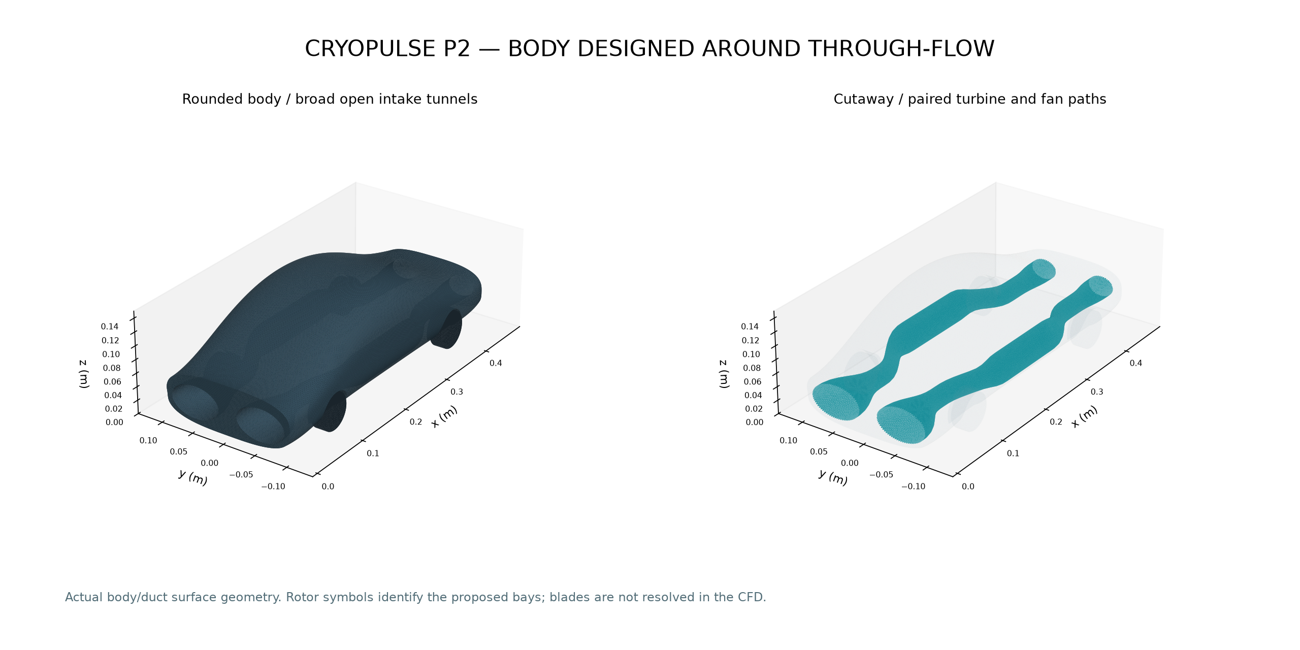
Actual CAD surface geometry, 1:10 scale, 480 mm body length. Rotor symbols show proposed bays; blades are not resolved in the CFD.
Airflow-first revision
Two broad elliptical nose openings replace the small P1 ports. The passages move inboard of the wheel clearances, then around the reserved central compartment. Rear neutral sections are straight.
The nominal nose opening area is 5.12 times P1's. Captured mass flow is a solver/measurement result, not assumed from that area ratio.
Premium and traceable
New 6061-T651 machined passages, Toray carbon/epoxy shell, C10100 thermal inserts and selected PEEK interfaces. Finished geometry, joints, roughness, actual mass and calibration remain build acceptance checks.
Wheel modules turn outward for downward reaction
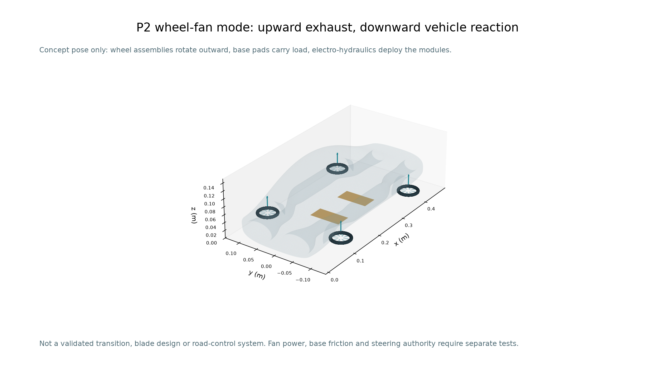
The whole module tilts; a separately driven impeller inside it supplies axial flow. Upward exhaust pushes the module down. Instrumented base pads carry transferred load in the fully deployed concept.
Deployment, pad friction and directional control are not validated by the body CFD. The illustrated deployed width is about 260 mm at 1:10 scale. This is a concept pose and separate analytical resource screen.
One architecture, separate power directions
Wheel-fan requirement screen
Choose a downward-force target for four 36 mm active rotors with 14 mm hubs. This asks what power an isolated static model requires; it does not assert achieved thrust.
Installed ground suction, inlet restriction, shrouds, crossflow and rotor/tyre interaction are not solved. This is not a universal limit on the architecture.
Base load and grip
No tyre or pad coefficient is invented. A conditional constant-friction screen reports the pad-to-tyre friction ratio needed to match the original axial force after full load transfer.
Not a stopping-distance or steering prediction. Compounds, load sensitivity, pad transients, dry/wet/ice behavior and directional control require measurements.
Hydraulics independent of wheel-brake pressure
An electromagnetic motor/pump or piston drives a separate hydraulic supply for wheel deployment and base-pad control. The DC bus and finite store supply its work. The module needs measured hinge torque, deployment timing, locking and pad-load feedback.
The analytical bore/stroke/direct-force cases are requirement examples, not qualified cylinder, accumulator or vehicle hardware.
Six completed geometry-based numerical runs
OpenFOAM v2412, 10 m/s air, 1:10 scale, steady RANS. P1 and passive P2 were each run on two local mesh levels. Charging and powered sensitivities use the same P2 coarse volume mesh.
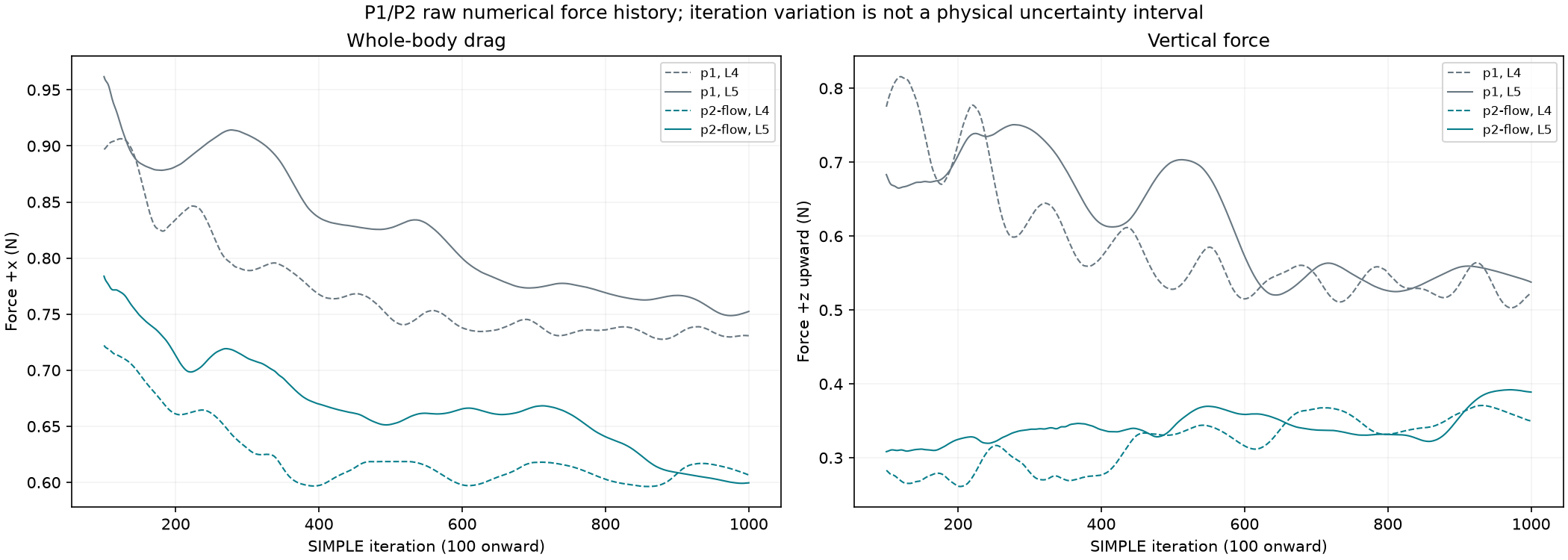
These are unvalidated research-shape comparisons. Strict steady convergence and experimental validation are not established; the figures are not gains over a high-end production vehicle.
| Variant | Mesh | Half-domain cells | Wall drag N | Rotor reaction N | Total axial N | Upward N |
|---|---|---|---|---|---|---|
| p1 | L4 | 143,192 | 0.7337 | +0.0000 | 0.7337 | +0.5312 |
| p1 | L5 | 735,372 | 0.7562 | +0.0000 | 0.7562 | +0.5514 |
| p2-flow | L4 | 144,247 | 0.6134 | +0.0000 | 0.6134 | +0.3630 |
| p2-flow | L5 | 727,102 | 0.6032 | +0.0000 | 0.6032 | +0.3843 |
| p2-charge | L4 | 144,247 | 0.6091 | +0.0049 | 0.6141 | +0.3613 |
| p2-powered | L4 | 144,247 | 0.6370 | -0.0483 | 0.5888 | +0.3509 |
Pressure/shear over the whole wall boundary is already included. Axial/vertical forces are mirrored by symmetry. Positive vertical force is lift, not downforce. Last-100-iteration means are not physical averages or confidence intervals.
Computed mode flow fields
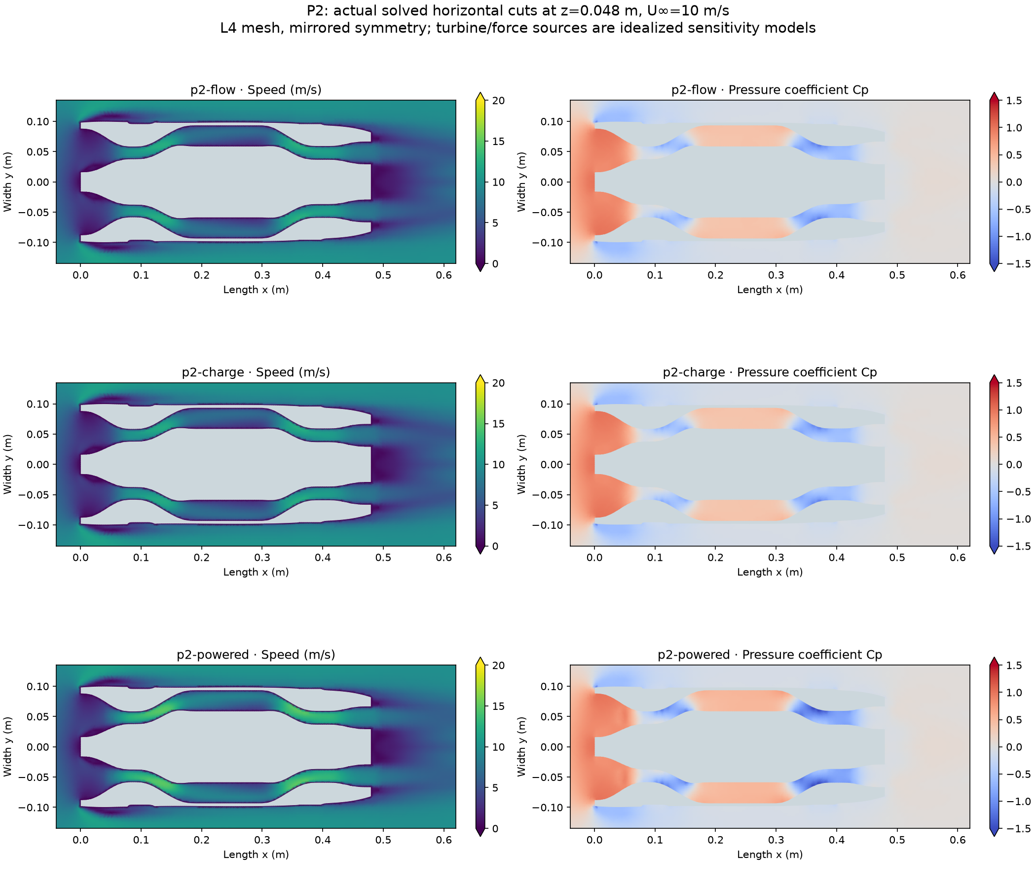
Grey regions are solid/no fluid in the cut. Same color scales; mirrored half-domain. Actuator coefficients/force are specified idealized inputs, not measured blades.
Charging includes the turbine reaction. Powered mode includes the opposite reaction of its specified force source. Fluid work is reported separately from electrical conversion; no efficiency or free thrust is silently credited.
Numerical checks
- p1-L4-U10-p2test: standard mesh passes; strict residual screen unmet; last-window force drift 0.81%.
- p1-L5-U10-p2test: standard mesh passes; strict residual screen unmet; last-window force drift 1.57%.
- p2-flow-L4-U10-p2test: standard mesh passes; strict residual screen unmet; last-window force drift 0.54%.
- p2-flow-L5-U10-p2test: standard mesh passes; strict residual screen unmet; last-window force drift 0.89%.
- p2-charge-L4-U10-p2test: standard mesh passes; strict residual screen unmet; last-window force drift 0.90%.
- p2-powered-L4-U10-p2test: standard mesh passes; strict residual screen unmet; last-window force drift 1.56%.
Extended concavity flags, missing prism wall layers, domain/transition modelling and pressure-corrector conventions are recorded in the methods. Rotor momentum balance remains an explicit check. No physical measurements have been made.
New premium materials, selected by function
New unused stock, traceable grade/condition and batch records. Prepreg requires documented shelf-life/out-time and storage. No parts were purchased.
| Component | Material | Incoming requirement |
|---|---|---|
| Split machined flow ducts, inlet and outlet blocks | 6061-T651 stress-relieved engineering plate | New plate, mill test report, alloy/temper/lot traceability; reject unidentified stock |
| Outer shell panels | Toray G-83CM carbon/epoxy prepreg system, supplier-confirmed carbon reinforcement and areal weight | New prepreg within manufacturer shelf life and out-time, documented storage/transport and batch cure record; no expired or unknown freezer stock |
| Removable thermal spreaders and heat-exchanger dummy inserts | C10100 / Cu-OFE / CW009A oxygen-free electronic copper | New certified material; purity and condition per supplier report; no recovered electrical scrap |
| Thermal spacers and carbon/aluminium isolation interfaces | New unfilled PEEK stock, supplier-certified grade | New stock and batch data; no recycled or unidentified polymer for these interfaces |
| Dry-air seam seals and removable-bay gasket | New supplier-certified PTFE gasket stock or qualified sealant selected after joint design | Original sealed packaging with lot and compatibility data |
| Precision mount, balance and fasteners | New calibrated laboratory six-component balance; new traceable fasteners and precision mount stock | Calibration certificate and adequate dead-load/moment capacity; no used uncalibrated transducer |
| Replaceable base friction pads and tyre-compound coupons | New supplier-formulated silica-filled tread-grade elastomer candidates for dry/wet/cold tests; compound and backing chosen from measured maps | New batch with formulation identifier, manufacture/storage history and supplier property sheet; no salvaged tyre tread |
| Wheel/fan carrier, hub, impeller and bearings | New supplier-qualified wheel/impeller components with traceable alloy/laminate and bearing specification | New components with rated speed/load and test provenance; no printable high-speed rotor supplied |
| Independent electromagnetic hydraulic drive | New matched motor/pump or electromagnetic piston, rated cylinders, valves, pressure sensor and compatible fluid/seals | New rated components with certificates and calibration; fluid selected against actual seals and temperatures |
Machined quote solids and acceptance targets
Four upper/lower STEP duct halves reopen as isolated solids and match as mirrored parts. The nominal geometric aluminium shell mass is about 0.60 kg for the pair, excluding joints, mounts, thermal hardware and changes after shop review.
Targets include Ra ≤0.8 micrometre, profile/joint step ≤0.05 mm and measured leakage below 1% at the test condition. These are requested acceptance targets, not fabricated results. Nominal wall sections, joint design, flanges and tooling access require DFM before manufacture.