More useful power
A replacement thermal path.
The old closed pressure loop is replaced by liquid pumping, engine-heat input and reheated nitrogen expansion. Both loops do not receive the same cold supply.
P4.1 · Theoretical research · Physical tests: 0
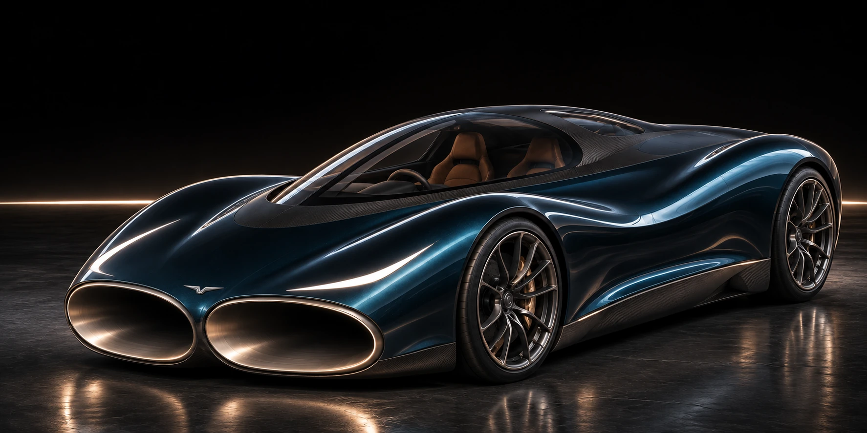
Could a car out-accelerate and out-brake a Bugatti Chiron? The updated CryoPulse model combines through-flow airways, powered downforce, adaptive braking and a cryogenic power stage.
Published Chiron: 2.4 s
Published Chiron: 32.6 s
Published Chiron: 491 m
Published Chiron: 41.96 s

One launch. One stop. No battery reset.
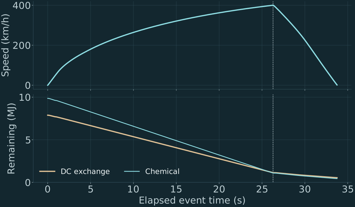
P4.1 carries 2,791 kg through the complete event. The fitted combustion-engine power curve stays the same. The battery still has a 10 MJ chemical operating window and an 8 MJ DC exchange limit.
| Event | Published Chiron | P4.0 model | P4.1 model |
|---|---|---|---|
| 0–100 km/h | 2.4 s | 2.06 s | 1.98 s |
| 0–200 km/h | 6.1 s | 6.17 s | 5.98 s |
| 0–300 km/h | 13.1 s | 13.65 s | 12.97 s |
| 0–400 km/h | 32.6 s | 28.53 s | 26.29 s |
| 400–0 km/h | 491 m | 463.9 m | 445.5 m |
| 0–400–0 km/h | 41.96 s | 36.41 s | 33.77 s |
Original Chiron reference, not the Super Sport or a matched physical test. Bugatti’s published 2017 run ↗ The CryoPulse engine and tyre laws are fitted requirements models, not a measured Chiron powertrain.
More useful power
The old closed pressure loop is replaced by liquid pumping, engine-heat input and reheated nitrogen expansion. Both loops do not receive the same cold supply.
More control
Seven pressure stages in each of three floor-flow paths. Commands stay within the modelled map. Braking uses the floor and upper vents together.
The same finite energy limits
An extra parallel battery string reduces cell loading. A 310 kW shared bus supports an effective wheel-assist envelope up to 280 kW. Their added mass is counted.
Cold liquid + engine waste heat → expansion work
Cold creates a usable temperature difference. The revised system pumps liquid nitrogen, heats it using the engine’s calculated exhaust flow, then expands it in two stages. The resulting electricity joins the same DC bus as the battery.
0.82 kg is spent cooling the cold pipe and pump before driving.
Hot metal starts at room temperature. The heat stream follows actual modelled engine work.
A finite nitrogen flow drives a generator. Pump and exhaust-blower demand are debited.
Traction, fans and hydraulics share their limits. Unaccepted generation is recorded as dumped heat.
Generator output less the stage’s pump, blower and control demand.
Startup and cold preparation are separate, explicit costs. The finite liquid store pays for both.
The remaining inventory carries forward. Boiloff receives no vehicle-weight benefit.
This player reads the saved simulation. Generator power is gross; the net figures above also subtract the stage’s electrical loads.
With the same hardware and mass carried in both runs, switching the thermal stage off gives 27.60 s to 400 km/h. Switching it on gives 26.29 s.
That is an isolated model comparison. It does not depend on subtracting the cold system’s weight from the off case.
The reversible minimum to prepare six kilograms of liquid nitrogen is about 4.45 MJ; a real supply chain costs more. Engine heat is also an explicit input.
This is a finite energy-conversion system. It is not a self-charging source or evidence of energy appearing from an empty region.
Same fitted engine · no speed limiter
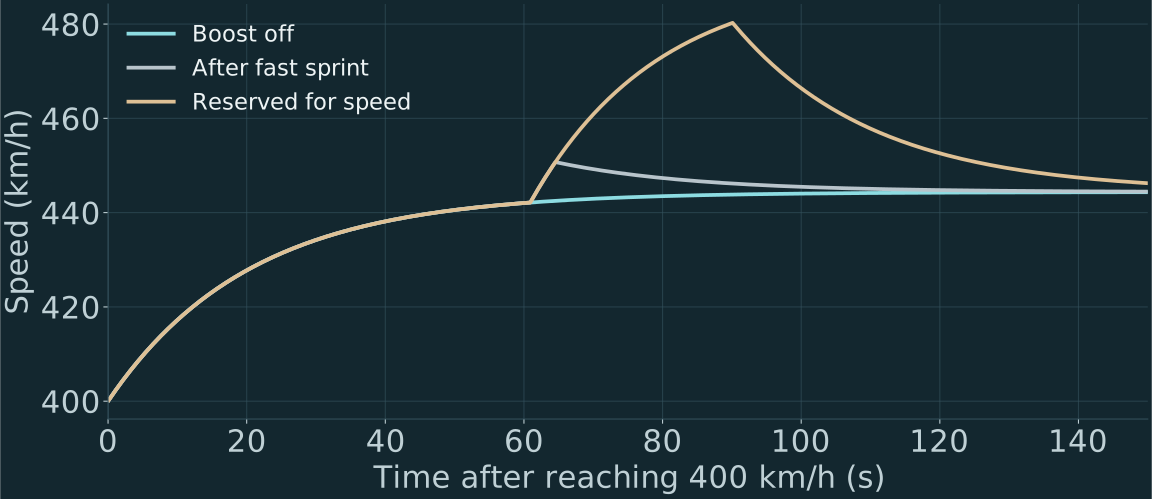
The same car can use different energy policies. A speed run keeps wheel boost off during acceleration and saves the remaining battery for a temporary high-speed pulse.
Engine-only force equilibrium after the sprint. Traction boost stays off; airflow and chassis services still draw electricity.
Own 0–400 launch: 26.29 s. Traction DC delivered after 400: 0.00 MJ. No fresh pack or nitrogen supply.
Reproducible calculations / retained limits
Nine established road and fault cases, plus eighteen new parameter draws. Each checks stopping, lane position, heading, suspension travel and the finite energy ledgers.
A passed finite scenario screen does not establish general road safety. The models still assume a smooth road and the stated tyre, seal and fan maps.
Halving the numerical timestep changes the dry stopping distance by 1.0 cm. The thermal stage closes first-law and exergy identities and has positive entropy generation.
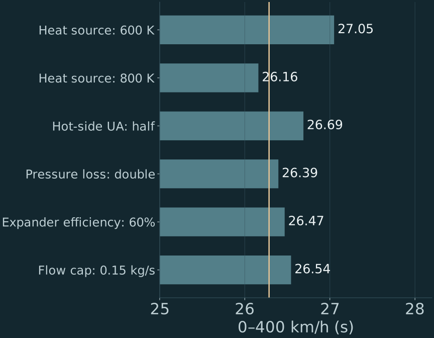
The equations show a conditional performance improvement with finite stores, mass and service loads. They do not show that a real car has reached these figures. The airframe drag target, road seal, installed motor map, heat-transfer performance, structural loads and new hardware packaging still need measurements and a detailed installation design.
P4.0 used an ambient-heat, recuperated pressure loop. P4.1 replaces it with open nitrogen expansion heated by engine exhaust. The original cooling-and-pressure idea remains a separate bench hypothesis; this new power stage does not prove a negative-energy or empty-space mechanism.
The extra parallel cells reduce loading per cell and add mass. The model still allows only the same 10 MJ chemical and 8 MJ DC exchange windows. Internal resistance, conversion loss, voltage limits and heating are calculated. Nameplate energy outside that operating window stays unavailable.
This is only the beginning of the full CryoPulse programme
The model now gives the hardware a job to meet. Further theoretical testing and physical demonstrations are to come. This release develops the airflow, energy and braking parts of a larger vehicle system.
Measure net force, pressure, mass flow and DC power together. Test a moving leakage gap. Include inlet capture and outlet momentum in the same force balance.
Measure liquid consumption, hot-stream heat, metal startup and net electrical output using rated laboratory hardware. Check pressure loss and heat transfer simultaneously.
Resolve the motor gearing, fan packaging and thermal structure. Run qualified body CFD, then tyre and suspension testing, before a high-speed prototype.
Door and occupant access, freezing-pressure cycles, magnetic actuation, cooperative magnetic collision research and wheel reconfiguration remain development packages. They receive no performance bonus in the figures above. The current release is not a percentage claim that the full plan is finished.