Conditional numerical study. Physical measurements: 0. The added geometry, mass, tyre, brake, pressure and power targets still need validation. This is a longitudinal component-coupled screen, not a demonstrated car or a yaw-stability result.
SAME MASS / SAME INITIAL STORES / SAME TYRE LAW
A new route to a shorter stop.
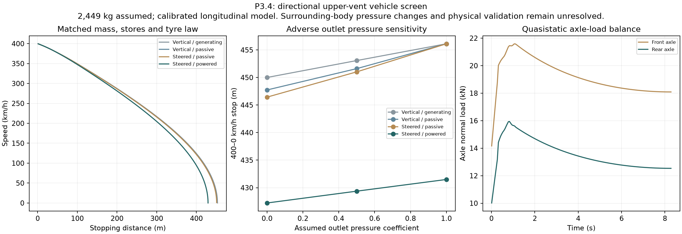
In the selected matched case, powered vectoring cuts the modeled 400–0 km/h distance from 451.6 m to 429.4 m. The comparison carries the energy remaining after the same acceleration run into braking.
429.4 mPowered, steered upper vents / Cp 0.5
4.9 %Shorter than the matched passive vertical route
2,449 kgAssumed vehicle mass, including 25 kg new hardware allowance
These numbers use the same fitted engine and earlier external shape target, with a finite 8 MJ usable pulse window and a 200 kW wheel-boost ceiling during acceleration. The model reaches 400 km/h in 24.24 s before this stop. Additional electrical energy is part of that performance case.
The published Chiron 400–0 km/h benchmark is 491 m. This revision refits one effective dry tyre parameter to that point; fitting is not independent validation. P3.4 adds an axle model and 25 kg beyond P3.3, so compare the matched rows here rather than subtracting figures across revisions.
—Vehicle speed
—Discharge angle / 90° is vertical
—Upper fan electrical draw
—Pulse energy remaining
—Front axle normal load
—Rear axle normal load
The calculated distance in the selected powered case is 429.4 m. Interactive model samples load when JavaScript is available.
Force schematic, not CFD streamlines or installed body geometry. The two drawn outlets represent the four proposed ports. A 200°/s assumed steering-rate limit is enforced in the model.
Upper route
Outlet Cp
400–0 distance
Stop time
Upper fan DC energy
Vertical / generating
0.0
450.0 m
8.71 s
0.00 MJ
Vertical / passive
0.0
447.7 m
8.68 s
0.00 MJ
Steered / passive
0.0
446.4 m
8.66 s
0.00 MJ
Steered / powered
0.0
427.2 m
8.25 s
1.73 MJ
Vertical / generating
0.5
453.1 m
8.75 s
0.00 MJ
Vertical / passive
0.5
451.6 m
8.73 s
0.00 MJ
Steered / passive
0.5
451.0 m
8.73 s
0.00 MJ
Steered / powered
0.5
429.4 m
8.28 s
1.73 MJ
Vertical / generating
1.0
456.1 m
8.79 s
0.00 MJ
Vertical / passive
1.0
456.1 m
8.79 s
0.00 MJ
Steered / passive
1.0
456.1 m
8.79 s
0.00 MJ
Steered / powered
1.0
431.5 m
8.31 s
1.74 MJ
All twelve rows start with the same mass and the same stores left after acceleration. Cp is a pressure-boundary sensitivity, not a measured property of a particular vent. Local nozzle reaction is included; changes in pressure forces on the surrounding body are withheld pending coupled flow work.
Actual model results. At Cp 1.0, the passive upper path cannot overcome the imposed outlet pressure, and the controller returns to the rear route.
POWER IS PART OF THE BRAKING SYSTEM
Recover it. Route it. Spend it once.
A shared electrical node.
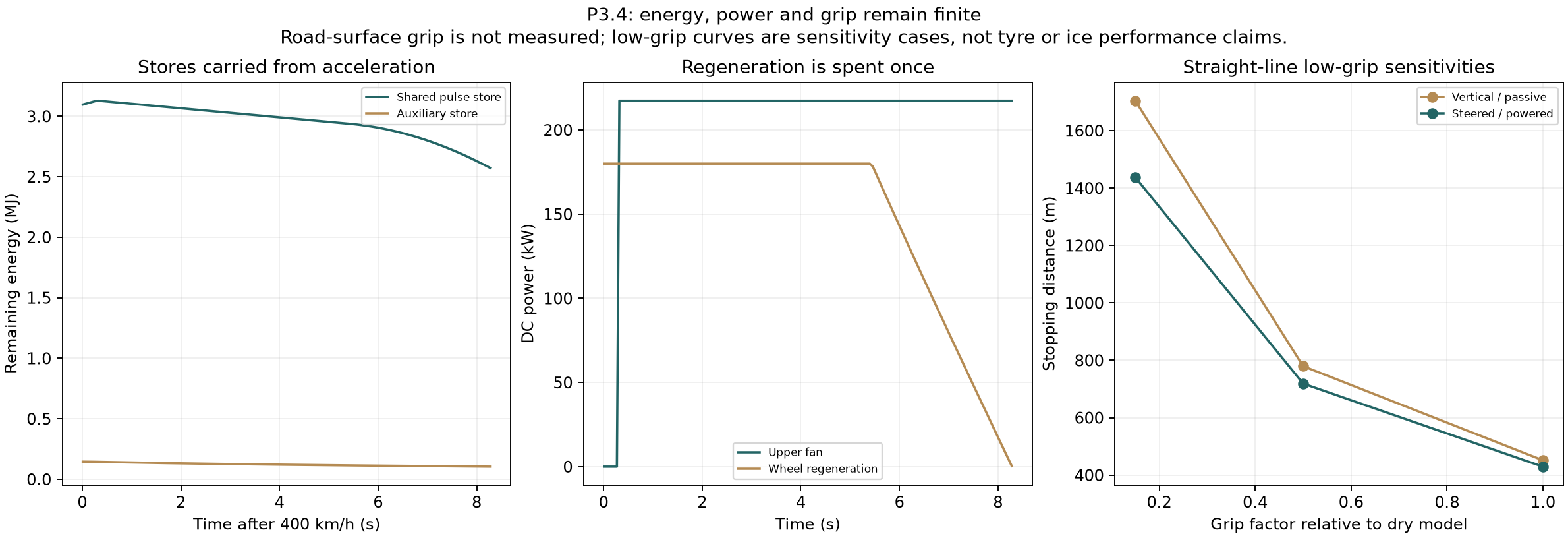
The upper fan, rotor startup and proposed DC/DC crossfeed share a 217.4 kW consumption limit. Wheel regeneration supplies that node and then charges the finite store. Friction braking handles the remaining wheel work.
The model accounts for a 20 kJ rotor start, 92% fan-motor conversion, 90% wheel-regeneration conversion and 95% DC/DC conversion. Assumed ratings still need component qualification.
Protection during a long stop.
A proposed 15 kW DC/DC crossfeed can supply the underfloor fan from the pulse store. A protected auxiliary reserve removes fan force when power is unavailable rather than retaining an unsupported benefit.
At the 0.15 grip-factor sensitivity, passive vertical braking changes from 1750 m with reserve protection alone to 1704 m with the proposed crossfeed. This remains a numerical design comparison.
With the smaller 1 MJ launch pulse, the car enters braking with zero pulse energy left. Regeneration must first recharge the 20 kJ startup allowance. In that explicit case the upper rotor starts at 0.12 s, and the conditional stop is 431.8 m. The store is not reset at 400 km/h.
GRIP AND TRAJECTORY
Keep the whole contact patch in the model.
The two axle normal loads include weight transfer, the upper reaction height and where the downforce acts. Front and rear brake limits are applied separately. A friction-circle demand reserves tyre capacity for a specified lateral acceleration.
Grip factor
Mode
Straight-line stop
Crossfeed delivered
0.5
Vertical / passive
780 m
0.0 kJ
0.5
Steered / powered
719 m
0.0 kJ
0.15
Vertical / passive
1704 m
78.2 kJ
0.15
Steered / powered
1438 m
47.8 kJ
Grip factors are relative to the dry fitted model. They are not measured wet-road, snow or ice coefficients.
The curve-demand stress test still fails. At the 0.15 grip factor, a simultaneous 0.15 g lateral demand becomes infeasible in the retained test. Those trajectories are excluded from road-following performance claims. The model does not yet establish protection against a spin.
The next controller model must add left/right wheel forces, yaw, steering and actuator failure states. The new power priority solves the recorded energy-exhaustion case; it does not solve every stability condition.
THE NEXT PHYSICAL DEMONSTRATION
Three outlets. One matched test.
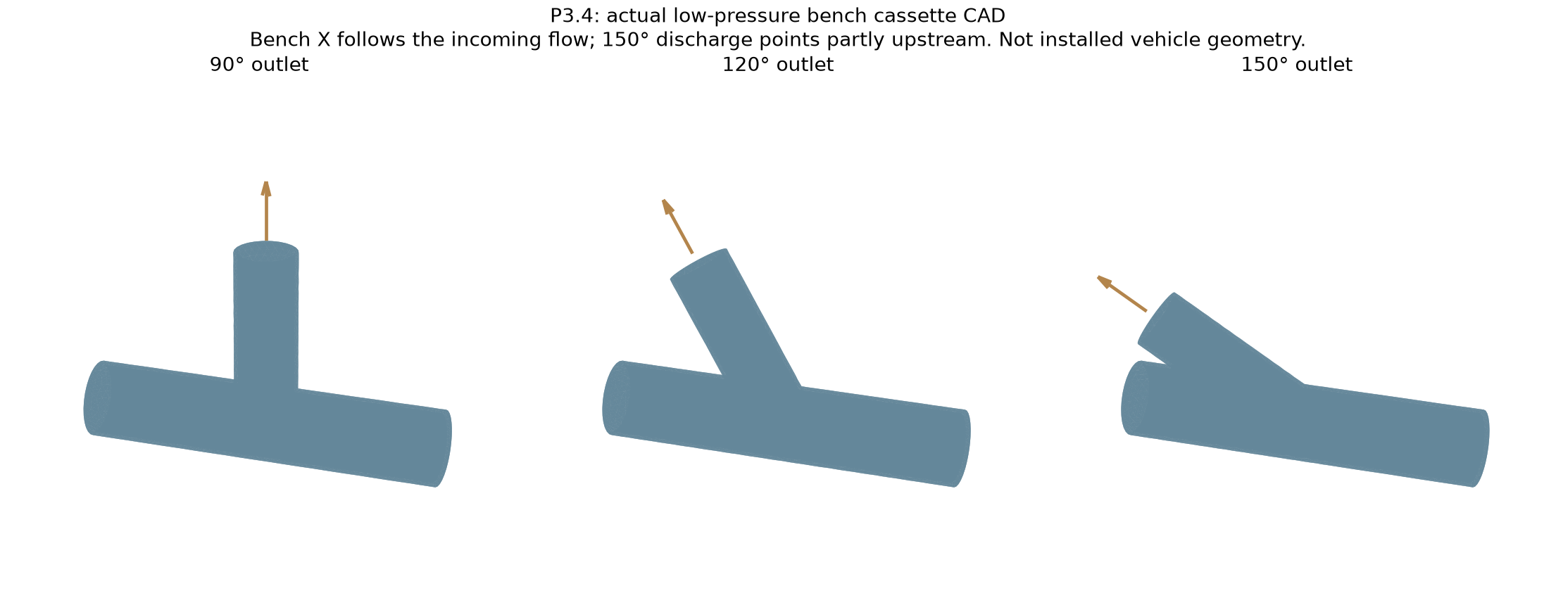
The new CAD defines 90°, 120° and 150° constant-bore outlet cassettes for the existing low-pressure dry-air rig. Measure both reaction components and pressure loss before assigning the full-size vents a benefit.
Metre-scale STEP imports and closed housing meshes checked. These are bench housings; seals, fixtures, instrumentation and actual fabrication remain to be completed.
The earlier matched warm/cold bench-core model remains the first cooling experiment. For the current neutral-temperature powered braking trajectory, an additional requirement screen asks what a 20 K bulk-air temperature drop would demand.
401 kWSampled peak air-cooling demand for the hypothetical 20 K drop
2.91 MJSample-integrated cold service over the braking trajectory
7.4 kgIdeal nitrogen fluid-only equivalent / container and losses omitted
The ideal nitrogen screen uses saturated liquid at atmospheric pressure and a 263 K terminal gas state. It is an enthalpy bound using CoolProp’s nitrogen equation of state, not a selected cooling installation.
This extra cold-store mass is not in the 25 kg vectoring allowance. No 20 K cooling effect, new cryogenic electricity or cooling-derived force improvement is credited to the vehicle figures. Heat-exchanger UA, pressure loss, frost, reset energy and the complete cold-system mass must be closed first.
3Bench CAD metre imports and closed surfaces checked
0Physical measurements
Source and vehicle energy balances, normal-load and pitch-moment limits, the empty-store startup and auxiliary protection checks pass. Refining speed, angle, power and time resolution changes the selected stopping distance by about 0.002%.
No new CFD is offered in this revision. The earlier P3.3 wake and mesh-quality limits remain unresolved. Installed pressure fields, seals, fan maps, tyres, real brake heat capacity and body dynamics still need independent evidence.
Full assumptions and limits
All geometry, tyre, actuator, brake-power and installed pressure inputs are assumptions, not measured CryoPulse hardware.
Quasistatic pitch balance is solved; suspension pitch dynamics, wheel slip and left/right yaw are not resolved.
Outlet pressure coefficient is an independent boundary sensitivity, not a CFD result or a prescribed function of outlet angle.
The force screen uses momentum and pressure thrust relative to the local outlet pressure, plus inlet momentum once. Changes to pressure forces on the surrounding body are withheld and need coupled CFD or force measurement.
The matched rear route is retained as a fallback if upper total pressure cannot overcome outlet pressure; reverse ingestion is excluded by a required isolation function.
The new 25 kg allowance is added to the prior conservative storage-mass case. It is not a qualified mass budget.
The engine curve, external drag target and fan/seal map remain the earlier unvalidated targets.
A grip factor is a sensitivity relative to the dry model, not a measured coefficient for a named road surface.
The 25 kg new-hardware allowance now includes the directional actuation and a proposed 15 kW DC/DC crossfeed. Voltage, isolation, ratings, thermal performance and actual hardware mass are unqualified.