A car works as one system. So should its model. Watch the tyres, upper vents, steering and stored energy respond together — then explore the cold-pressure idea at its source.
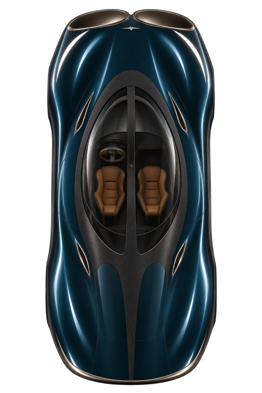
Calculated trajectories and forces. Illustrative vehicle styling. The vehicle has not been built.
Through-flow concept · wheel control · upper-vent reaction
Conditional model results. Physical measurements: 0. These calculations identify a possible design and its requirements. They do not establish real-car performance or superiority over a measured Bugatti Chiron.
18.7%Shorter modelled dry stop Air systems on vs off, at the same mass
9 conditionsBoth virtual controllers stop within the stated lane and heading test limits
6.82%Ideal sealed-gas pressure reduction 20°C → 0°C in a rigid vessel
56.3 kJ/kgSeparate nitrogen recovery calculation Net DC before unallocated auxiliaries
01 · Forces, direction and energy
Watch the stop. Follow the forces.
Start with the complete air system enabled and disabled. Then replay unequal grip, a crosswind, a lost upper port or unavailable motor. Every trajectory comes from the recorded numerical runs.
400–0 km/h · coupled driving model
Same assumed mass, tyres and finite stores. Air systems enabled and disabled.
Same mass · air systems off
Matched mass and stores
543.3 mModelled 400–0 km/h stop
400 km/hSpeed
0.00°Heading error
0.00 mLateral position
0.0 kWUpper fan DC input
3.06 MJPulse store remaining
0.0 kWWheel regeneration to DC
0.0 kWShared pulse-node DC draw
145.8 kJProtected auxiliary store
CryoPulse · air systems operating
Dry straight stop
441.8 mModelled 400–0 km/h stop
400 km/hSpeed
0.00°Heading error
0.00 mLateral position
0.0 kWUpper fan DC input
3.06 MJPulse store remaining
0.0 kWWheel regeneration to DC
0.0 kWShared pulse-node DC draw
145.8 kJProtected auxiliary store
Recorded trajectory
Air systems offAir systems on
Car shape and air paths are illustrations, not CFD. Wheel markers show braking force relative to normal load; the separate plot uses actual model distances. The shaded band marks a ±0.8 m centre-path guide. The pass check includes the rotated vehicle footprint within a 3.6 m corridor and peak heading below 3°. These are research thresholds.
Grip multipliers are model sensitivities, not measured wet, snow or ice coefficients. The steering and braking model does not know an invisible road boundary: it follows a specified straight reference and reacts to delayed vehicle-state feedback.
02 · Read the comparison correctly
A useful gain. A complete record.
441.8 m with air systems operating
The matched air-off case takes 543.3 m. Both start at 400 km/h with the same 2,464.4 kg mass, effective tyre model, brake limits and stored energy. That is a 18.7% conditional reduction in this dry, straight-line scenario.
Removing an assumed 270 kg air-hardware allowance from the air-off model gives 522.2 m. This sensitivity separates some mass cost from the aerodynamic benefit; it is not a measured production-car reference.
Where the Chiron fits
The published Chiron reference is 491 m from 400 km/h. The earlier effective tyre parameter was fitted to that point, so the CryoPulse result is a design projection built on a calibrated baseline. It is not independent proof that a real car beats the Chiron.
Same revised CryoPulse hardware · virtual controller comparison · all start at 400 km/h
Condition
Wheel ESC Fixed upper route
Airflow-aware coordination
Coordinated peak lateral position
Coordinated peak heading
Both controllers
Dry straight stop
441.8 m
441.8 m
0.000 m
0.000°
Within stated limits
Unequal left/right grip
872.5 m
881.1 m
0.431 m
1.248°
Within stated limits
Crosswind pulse
620.1 m
620.1 m
0.184 m
0.892°
Within stated limits
Unequal grip and wind
863.7 m
872.8 m
0.452 m
1.252°
Within stated limits
One upper port lost
444.7 m
444.7 m
0.009 m
0.044°
Within stated limits
Unequal grip and port loss
874.7 m
882.2 m
0.435 m
1.267°
Within stated limits
Low-grip straight stop
1266.9 m
1266.9 m
0.000 m
0.000°
Within stated limits
Low grip and port loss
1284.8 m
1284.8 m
0.017 m
0.048°
Within stated limits
Upper motor unavailable
678.0 m
678.0 m
0.000 m
0.000°
Within stated limits
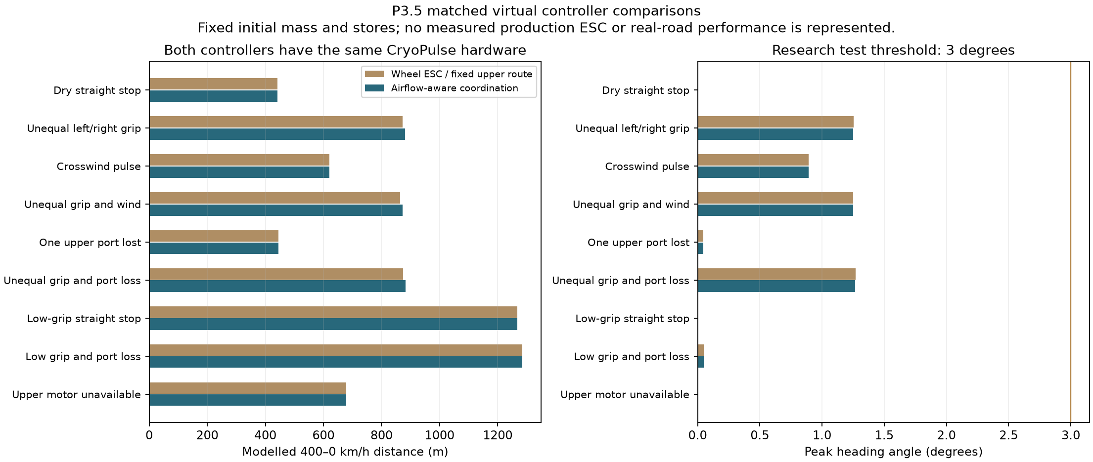
Both virtual controllers already have the CryoPulse fan, underfloor suction and upper-route hardware. Air trim adds roughly 8–9 m in the three unequal-grip cases; its direction metrics change only slightly. It earns no claim of uniformly shorter stops. The stronger current result is the revised architecture meeting all nine stated conditions.
All nominal results are shown, including conditions where extra airflow coordination does not improve distance. Two additional controller runs use a held-out combined condition.What changed from the initial design?
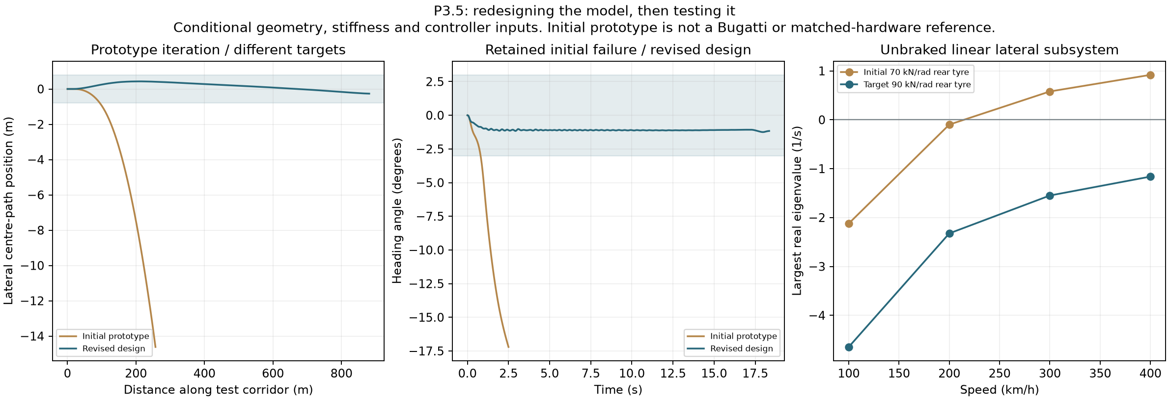
The retained first prototype failed the unequal-grip corridor test: it reached about 15 m lateral deviation and 17.3° heading, with no completed stop. It is not a production-car comparator.
The revised design sets rear cornering stiffness to 90 kN/rad per tyre instead of 70, adds dynamic steering feedback, keeps grip estimates from drifting upward without informative measurements, and reserves tyre capacity for direction control. The airflow planner predicts how each command changes wheel loads. Those stiffness, sensing and actuator targets still need hardware qualification.
The initial trace ends when the test aborts. Its travelled distance is not a stopping-distance result.What about acceleration and top speed?
This revision uses the prior finite-energy acceleration model to initialise the braking event. With the stated engine envelope, electrical traction boost, launch suction, an 8 MJ initial pulse store and the new mass, it calculates 2.07 s to 100 km/h and 24.39 s to 400 km/h. About 3.06 MJ remains before braking. These acceleration figures inherit the earlier longitudinal assumptions; four-wheel yaw dynamics are applied to the braking phase.
P3.5 does not establish a new top-speed result. Earlier unrestricted speed screens remain separate model cases with their own power, drag and pulse assumptions. Explore the earlier performance comparison ↗
03 · Back to the original cold-flow idea
Cool the air. Watch the pressure change.
The useful mechanism is a pressure difference. Cooling a sealed gas lowers its pressure. Open a path to warmer ambient air and air can flow in — until that difference is used up.
This gives us a simple demonstration of the original idea. Start with 10 litres of dry air at 20°C and atmospheric pressure. Keep the volume fixed and cool it to 0°C. The ideal-gas pressure falls to 94.41 kPa absolute.
The colder gas can admit about 0.882 g more air before equalising, if held at 0°C. A pressure difference can do work, but the cooling and reset require energy. No new energy appears when the space fills.
The 69.1 N value is a pressure force on a fixed 100 cm² sensing surface. It is not vehicle thrust. The work figure is an ideal upper bound for a reversible fill expander, not a measured tiny turbine.
Animation timing is illustrative. No flow rate is predicted.
6.91 kPaInitial pressure deficit · 6.82%
0.882 gFinite additional air at cold equalisation
69.1 NInitial fixed-face pressure force · 100 cm²
172.8 JSealed gas cooling alone · walls excluded
2.573 JIdeal gross fill-work upper bound
04 · Recover useful energy without counting it twice
One finite cold store. Heat recovery in series.
The separate nitrogen calculation pumps cold liquid, warms it with an available heat source, expands the resulting dry gas through a generator, then uses the remaining cold for another cooling duty.
01 · Stored resource77.35 K
Liquid nitrogen at atmospheric pressure. A finite offboard-prepared cold store.
02 · Liquid pump10 bar
Electrical pump input is deducted. Pump efficiency target: 65%.
03 · Heat uptake200 K
Heat is supplied before expansion. It is an explicit input.
04 · Expand & generate135.36 K
Expansion to atmospheric pressure. Expander efficiency target: 65%.
05 · Remaining cooling263.15 K
Further heat uptake after expansion. The same nitrogen is used once.
Move through the finite inventory
0.0 kJNet DC before unallocated auxiliaries
2.0 kgCold inventory remaining
0.0 kJHeat absorbed across both stages
0 JEnergy credited to the driving model
112.5 kJ from the selected 2 kg case
The state calculation closes its first-law and exergy balances. The net result subtracts the specified liquid-pump motor input and generator loss. The selected case has dry gas at the expander and a positive heat-exchanger temperature approach.
Circulation power, valve losses, real exchanger area, tank and equipment mass, boil-off and replenishment have not been closed. Nitrogen manufacture and re-liquefaction need an offboard energy account before any whole-cycle efficiency claim.
This is a thermodynamic branch to develop, with zero driving-energy credit in the results above. It is not self-charging propulsion.
A shared plenum, four outlets and four gate discs. The interactive view uses the mesh of the delivered STEP geometry.
Three discrete poses were checked for solid overlap. Independent STEP imports verify five solids and a 240 mm housing length. The main inlet bore is 84.4 mm; each outlet is 27.64 mm.
The next detail design must add shafts, seats, seals, mounts and actuators. The nominal gate clearance is not an airtight seal, and the three-pose check does not establish continuous motion or structural strength. This is a low-pressure bench layout, not the car’s installed duct geometry.
For the assumed axle geometry and front stiffness, the linear unbraked bicycle model requires rear cornering stiffness of at least 76.4 kN/rad per tyre for nonnegative understeer. The 90 kN/rad target satisfies that condition. The original 70 kN/rad target does not; its linear model has a critical speed near 210 km/h.
This is a mathematical result within a specified model. It does not establish nonlinear braking stability, measured tyre characteristics or a certified speed limit. The numerical scenarios add saturation, finite actuator response, sensing delay and energy limits.
The wheel model uses force actuators and an ideal inner slip-limiting loop. It does not solve wheel rotational speeds, a measured tyre-slip curve or actual hydraulic pressure. Pitch and roll transfer are quasistatic. Tyre stiffness and grip estimation, brake heat fade, sealing, steering authority, fan maps, valve dynamics and the equipment mass all need measured data.
Local outlet reaction and inlet momentum are included, but changed pressure forces on the surrounding vehicle body are withheld. Installed full-car CFD and force measurements remain open; the earlier wake and mesh-quality gates are not declared passed here. These deterministic scenarios do not establish universal stability.
How the electrical account is kept finite
The braking event follows a separately calculated acceleration run from an initial 8 MJ pulse store. Approximately 3.06 MJ remains for braking. The shared pulse node is limited to about 217.4 kW. Fan startup, valve/vector movement and DC/DC input share that node. Wheel regeneration can replenish the store within its capacity; ground suction, steering and control loads draw from the protected auxiliary supply. Neither cold-pressure work nor nitrogen-generation potential is added to that account.
The next gains have to come from closing the hardware requirements: an installed body and duct shape, measured wheel and fan maps, a practical cold-recovery assembly, and control that keeps the car composed as conditions change.
Next engineering steps
Measure the shared manifold’s forces, leakage and power. Fit measured tyre and actuator data. Add suspension transients and wheel-speed dynamics. Rework air trim where it increases distance without a useful direction benefit. Then repeat the combined driving cases with those measured inputs.
The wider CryoPulse plan
Acceleration, unrestricted speed, thermal management, materials, accessible doors and the complete luxury package remain part of the programme. This revision closes a numerical coordination stage; it does not finish the vehicle or claim a percentage of engineering completion.