
Prepared development model
P4.6 / THE CONNECTED PROTOTYPE
Use the air.
Recover the heat.
Could a car out-accelerate and out-brake a Bugatti Chiron? The next CryoPulse model brings airflow, cold, waste heat and the drivetrain into one energy account.
Development projections. Vehicle not built.
Physical measurements: 0.
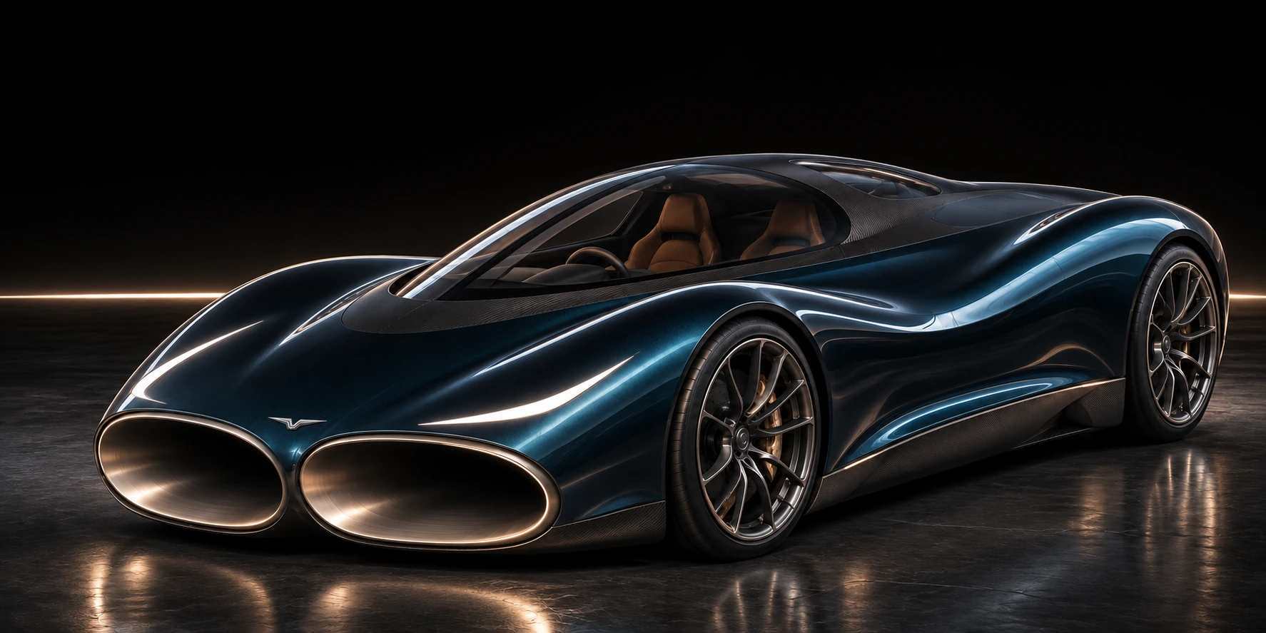
Same fitted engine envelope
Stores carried from launch
Conditional prepared-mode results. These require the stated body drag, fan, tyre, heat-transfer and brake targets. They are not measured CryoPulse performance or independent proof of superiority.
THREE PHYSICAL JOBS / ONE CAR
The air has a job.
So does the cold.
The floor adds tyre load. The main passage carries air through the body. One finite nitrogen stream first absorbs heat, then expands to produce shaft work. Each source and loss is counted once.
AIR / PRESSURE AND MOMENTUM
More contact force.
A gentler route through.
The new passage runs above the cabin rather than repeatedly bending around the wheels. The proposed floor covers 4.14 m². Its pressure difference adds downward force; the fans, leaks, suspension and capture drag still have to be paid.
Routing schematic, not a solved flow field. The shared floor-to-main junction is a separate component study; its saving is not credited in these driving figures. The driving replay retains an independent floor outlet.
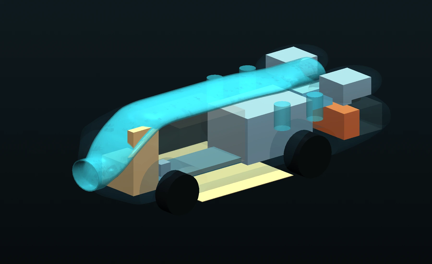
The declared cabin and wheel-sweep clearance checks pass. Boxes reserve component space; the complete suspension, doors, pressure hardware and structure still need detailed design.
A wider pressure floor.
About 14.7% more pressure area than P4.4, with a 7% increase in perimeter. The event model also pays for a larger fan bank and reinforcement.
One finite cold charge.
Preparation boiloff, reserved hold-up and standby losses are debited. Nitrogen passes through battery heat, engine coolant and exhaust stages once.
Recovered shaft work.
Liquid is pumped, heated and expanded in two stages. A proposed geared coupling sends useful work to the drivetrain, with pump power and coupling losses included.
ONE SPRINT / CONTINUOUS STORES
Watch the model
do the work.
Preparation, launch and stopping use carried battery, nitrogen, heat and rotor states. The timed run starts after the declared preparation. Nothing is refilled at 400 km/h.
BEFORE THE CLOCK STARTS
6 minutes of modeled warm-up, then 6 seconds of floor preparation. Warm-up uses 54 MJ of fuel energy at the stated high-idle source target. Controls, pumps, blower demand and the prelaunch nitrogen ramp are also charged. The heat cores begin at ambient temperature.
CryoPulse development modelPublished Chiron checkpoints
SPEED
THERMAL SHAFT POWER
FLOOR FORCE
NITROGEN REMAINING
| Prepared sprint | Chiron published | CryoPulse model |
|---|---|---|
| 0–100 km/h | 2.4 s | 2.01 s |
| 0–200 km/h | 6.1 s | 5.83 s |
| 0–300 km/h | 13.1 s | 13.15 s |
| 0–400 km/h | 32.6 s | 27.39 s |
| 400–0 km/h stopping distance | 491 m | 441.57 m |
| 0–400–0 km/h | 41.96 s | 34.63 s |
The fitted reference-engine power envelope is unchanged. The CryoPulse car is heavier and has extra electrical and prepared-cold resources. The 0–300 projection remains slightly slower. Published Chiron data are comparison points, not a measured test of this new car.
SWITCH RECOVERY OFF / RETAIN THE SAME CAR
Does the heat route add anything?
In this matched-car calculation, recovery changes 0–100 from 2.13 to 2.01 s, and 0–400 from 32.16 to 27.39 s. That is a 4.78 s reduction in the same requirements model.
Same candidate mass, engine, electrical allowance, preparation duration, peak-current policy and controller. The disabled case retains the hardware. This isolates the recovery function inside the requirements model.
A DIFFERENT POLICY / A SEPARATE SPEED EVENT
Keep a reserve
for the long run.
Speed mode holds the nitrogen for late assistance and uses more of the same physical battery’s SOC range. Its earlier acceleration is different. Its peak is not combined with the quickest sprint.
No electronic speed limiter. Same fitted engine envelope, extrapolated beyond 400 km/h. Gearing, tyre speed capability, cooling and high-speed stability remain unqualified.
CONDITIONAL TEMPORARY PEAK489.1km/h
This separate run reaches 400 km/h in 32.21 s, then carries the same stores into the speed continuation. Its peak is temporary, not a demonstrated sustainable road speed.
Read the complete mode definitions ↗WHAT IS CLOSED / WHAT IS STILL OPEN
A stronger model.
A testable proposal.
A simulation can demonstrate consistency and expose a bottleneck. Measurements must establish whether the proposed parts achieve their targets.
The accounts close.
Separate vehicle, battery, nitrogen, coolant, exhaust and hot-metal balances are checked. Gear synchronisation energy is dissipated and charged. With the new mechanisms disabled, the extended launch kernel reproduces the frozen parent exactly.
Repeat the computation.
Halving the mechanical step changes 0–400 time by 1.33 ms and stopping distance by 0.228 m. This checks numerical sensitivity, not the truth of the component targets.
Earn the installed performance.
The external drag area is still a 0.65 m² target and the main-route loss coefficient a 0.4 target. Current duct results need further refinement; exterior meshes have failed checks. No new drag reduction has been validated by CFD.
Build the evidence.
The 4.5 MW transient brake package, pressure containment, expander efficiency, installed mass, tyre load/speed behaviour and thermal maps remain to be qualified. The low-pressure cold-flow rig is a separate experiment; it cannot validate a hypercar by itself.
The main assumptions, in plain sight
- Development mass: 3,201.2 kg, including maximum wet nitrogen mass throughout.
- Same fitted effective engine-power curve; no measured new powertrain or gear-shift map.
- Same tyre friction law. Larger caliper piston area, added rotor mass and paid hydraulic capacity; no invented grip bonus.
- 216s11p battery. Sprint: 16 MJ chemical / 12.8 MJ DC exchange ceilings, including preparation. Speed mode: physical SOC window from 60% to 20%.
- A proposed 3.09 / 2.4 two-speed electric drive. The 150 ms shift interruption, 1 kJ actuation and rotor-energy loss are included.
- Up to 900 Arms for the first 20 seconds, then the 500 Arms envelope. This remains below the supplier’s 30-second peak window; installed coolant, current and motor performance still need qualification.
- Two heat-exchanger banks with 17 kg of hot metal, finite heat capacity and paid exhaust extraction. Heat-transfer and pressure-loss correlations are sizing requirements.
- The shared floor-to-main branch has an encouraging standalone pressure-node calculation, but its saving is excluded from these vehicle figures.
Download the model and layout ↘Results and audit ↗Deployable website ZIP ↘Frozen P4.4 study ↗Cold-flow bench programme ↗
Reference data: Bugatti Chiron technical data. Electrical limits: Cascadia CM350SiC and iM-375. The liquid-cooled air-motor continuous power is corrected to 68 kW per unit using EMRAX 228 v1.7; the earlier airflow study has been recalculated.
This is only the beginning. Braking, acceleration and thermal recovery are parts of the wider CryoPulse plan. Further theoretical testing and physical demonstrations are to come. Overall programme completion has not been quantified.